Nissan Cube. Manual - part 812
B2603 SHIFT POSITION
SEC-59
< DTC/CIRCUIT DIAGNOSIS >
[WITH INTELLIGENT KEY SYSTEM]
C
D
E
F
G
H
I
J
L
M
A
B
SEC
N
O
P
4.
Check continuity between transmission range switch harness connector and ground.
Is the inspection result normal?
YES
>> GO TO 6.
NO
>> Repair or replace harness.
6.
CHECK TRANSMISSION RANGE SWITCH
SEC-60, "Component Inspection (Transmission Range Switch)"
.
Is the inspection result normal?
YES
>> GO TO 12.
NO
>> Replace transaxle assembly. Refer to
7.
CHECK CVT SHIFT SELECTOR POWER SUPPLY
1.
Turn ignition switch OFF.
2.
Disconnect CVT shift selector (detention switch) connector.
3.
Check voltage between CVT shift selector (detention switch) harness connector and ground.
Is the inspection result normal?
YES
>> GO TO 9.
NO
>> GO TO 8.
8.
CHECK CVT SHIFT SELECTOR POWER SUPPLY CIRCUIT
1.
Disconnect BCM connector.
2.
Check continuity between CVT shift selector (detention switch) harness connector and BCM harness con-
nector.
3.
Check continuity between CVT shift selector (detention switch) harness connector and ground.
Is the inspection result normal?
YES
>> Replace BCM. Refer to
BCS-88, "Removal and Installation"
NO
>> Repair or replace harness.
9.
CHECK CVT SHIFT SELECTOR CIRCUIT (BCM)
1.
Disconnect BCM connector and IPDM E/R connector.
2.
Check continuity between CVT shift selector (detention switch) harness connector and BCM harness con-
nector.
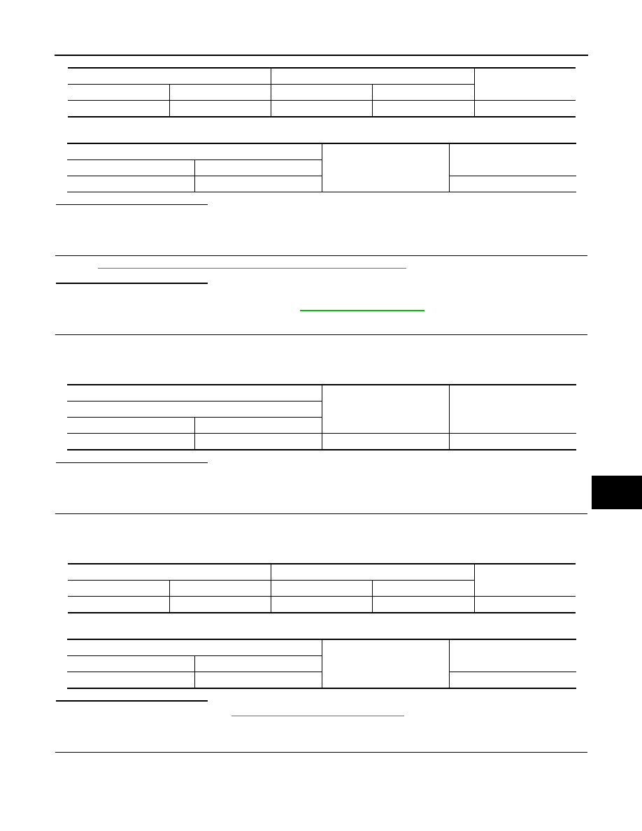
Transmission range switch
BCM
Continuity
Connector
Terminal
Connector
Terminal
F21
2
M71
102
Existed
Transmission range switch
Ground
Continuity
Connector
Terminal
F21
2
Not existed
(+)
(–)
Voltage (V)
(Approx.)
CVT shift selector (detention switch)
Connector
Terminal
M58
7
Ground
12
CVT shift selector (detention switch)
BCM
Continuity
Connector
Terminal
Connector
Terminal
M58
7
M71
104
Existed
CVT shift selector (detention switch)
Ground
Continuity
Connector
Terminal
M58
7
Not existed