Nissan Cube. Manual - part 808


  Index      Nissan     Nissan Cube (2014 year) - Service and Repair Manual


Search            


Content   ..  806  807  808  809   ..


Nissan Cube. Manual - part 808


B2198 NATS ANTENNA AMP.

SEC-43

< DTC/CIRCUIT DIAGNOSIS >

[WITH INTELLIGENT KEY SYSTEM]

C

D

E

F

G

H

I

J

L

M

A

B

SEC

N

O

P

3.

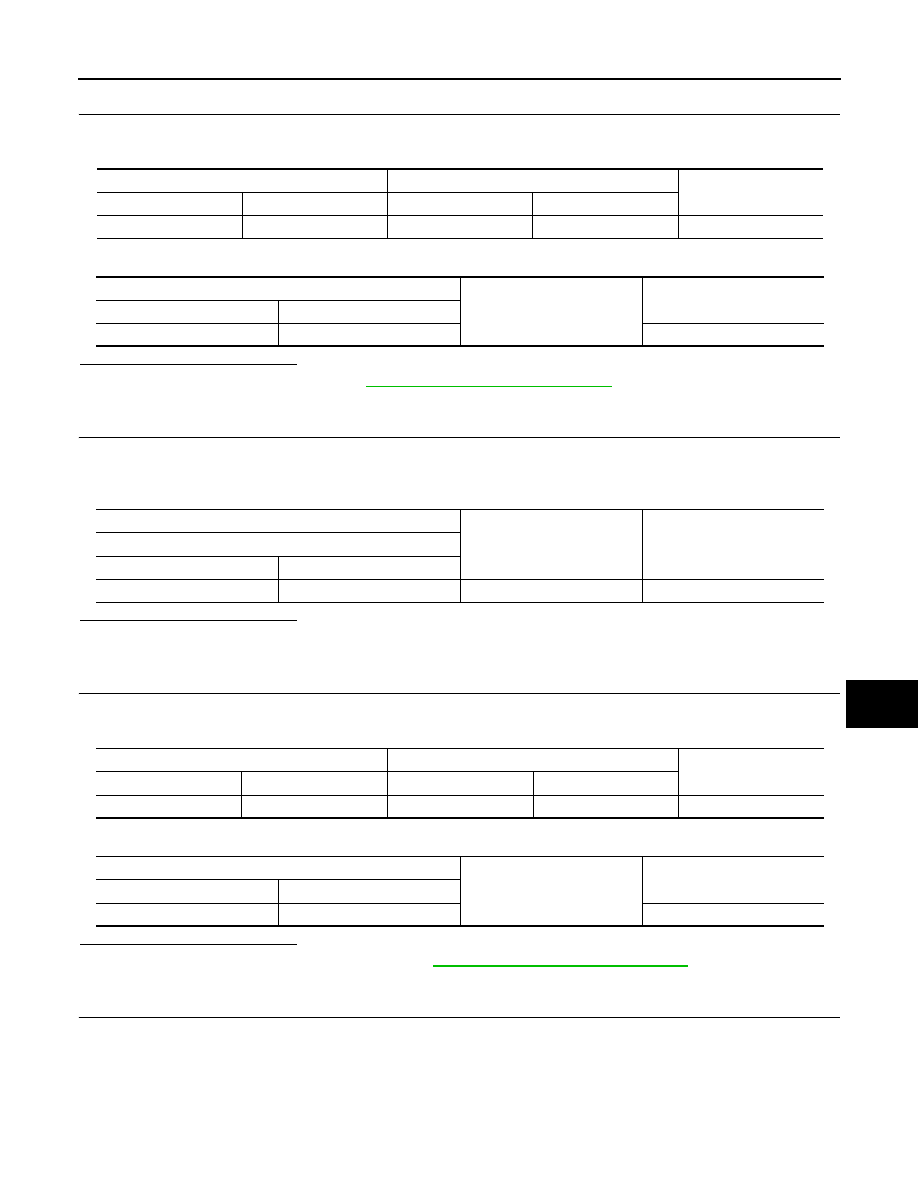
CHECK NATS ANTENNA AMP. POWER SUPPLY CIRCUIT

1.

Disconnect IPDM E/R connector.

2.

Check continuity between IPDM E/R harness connector and NATS antenna amp. connector.

3.

Check continuity between IPDM E/R harness connector and ground.

Is the inspection result normal?

YES

>> Replace IPDM E/R. Refer to 

PCS-34, "Removal and Installation"

.

NO

>> Repair or replace harness.

4.

CHECK NATS ANTENNA AMP. OUTPUT SIGNAL 1

1.

Connect NATS antenna amp. connector.

2.

Disconnect BCM connector.

3.

Check voltage between BCM harness connector and ground.

Is the inspection result normal?

YES

>> GO TO 6.

NO

>> GO TO 5.

5.

CHECK NATS ANTENNA AMP. OUTPUT SIGNAL CIRCUIT 1

1.

Disconnect NATS antenna amp. connector.

2.

Check continuity between BCM harness connector and NATS antenna amp. connector.

3.

Check continuity between BCM harness connector and ground.

Is the inspection result normal?

YES

>> Replace NATS antenna amp. Refer to 

SEC-174, "Removal and Installation"

.

NO

>> Repair or replace harness.

6.

CHECK NATS ANTENNA AMP. COMMUNICATION SIGNAL

1.

Connect BCM connector.

2.

Check voltage between BCM harness connector and ground using analog tester.

IPDM E/R

NATS antenna amp.

Continuity

Connector

Terminal

Connector

Terminal

E14

45

M26

1

Existed

IPDM E/R

Ground

Continuity

Connector

Terminal

E14

45

Not existed

(+)

(–)

Voltage (V)

(Approx.)

BCM

Connector

Terminal

M68

21

Ground

Battery voltage

BCM

NATS antenna amp.

Continuity

Connector

Terminal

Connector

Terminal

M68

21

M26

2

Existed

BCM

Ground

Continuity

Connector

Terminal

M68

21

Not existed

SEC-44

< DTC/CIRCUIT DIAGNOSIS >

[WITH INTELLIGENT KEY SYSTEM]

B2198 NATS ANTENNA AMP.

Is the inspection result normal?

YES

>> GO TO 7.

NO

>> Replace NATS antenna amp. Refer to 

SEC-174, "Removal and Installation"

.

7.

CHECK NATS ANTENNA AMP. OUTPUT SIGNAL 2

1.

Disconnect BCM connector.

2.

Check voltage between BCM harness connector and ground.

Is the inspection result normal?

YES

>> GO TO 9.

NO

>> GO TO 8.

8.

CHECK NATS ANTENNA AMP. OUTPUT SIGNAL CIRCUIT 2

1.

Disconnect NATS antenna amp. connector.

2.

Check continuity between BCM harness connector and NATS antenna amp. connector.

3.

Check continuity between BCM harness connector and ground.

Is the inspection result normal?

YES

>> Replace NATS antenna amp. Refer to 

SEC-174, "Removal and Installation"

.

NO

>> Repair or replace harness.

9.

CHECK NATS ANTENNA AMP. COMMUNICATION SIGNAL

1.

Connect BCM connector.

2.

Check voltage between BCM harness connector and ground using analog tester.

Is the inspection result normal?

YES

>> GO TO 10.

NO

>> Replace NATS antenna amp. Refer to 

SEC-174, "Removal and Installation"

.

10.

CHECK NATS ANTENNA AMP. GROUND CIRCUIT

(+)

(–)

Condition

Voltage (V)

(Approx.)

BCM

Connector

Terminal

M68

21

Ground

Intelligent Key backside is contacted 
to push-button ignition switch, turn ig-
nition switch ON.

Just after pressing push-button igni-
tion switch. Pointer of analog tester 
should move.

(+)

(–)

Voltage (V)

(Approx.)

BCM

Connector

Terminal

M68

25

Ground

Battery voltage

BCM

NATS antenna amp.

Continuity

Connector

Terminal

Connector

Terminal

M68

25

M26

3

Existed

BCM

Ground

Continuity

Connector

Terminal

M68

25

Not existed

(+)

(–)

Condition

Voltage (V)

(Approx.)

BCM

Connector

Terminal

M68

25

Ground

Intelligent Key backside is contacted 
to push-button ignition switch, turn ig-
nition switch ON.

Just after pressing push-button igni-
tion switch. Pointer of analog tester 
should move.

B2198 NATS ANTENNA AMP.

SEC-45

< DTC/CIRCUIT DIAGNOSIS >

[WITH INTELLIGENT KEY SYSTEM]

C

D

E

F

G

H

I

J

L

M

A

B

SEC

N

O

P

1.

Disconnect NATS antenna amp. connector.

2.

Check continuity between NATS antenna amp. harness connector and ground.

Is the inspection result normal?

YES

>> GO TO 11.

NO

>> Repair or replace harness.

11.

CHECK INTERMITTENT INCIDENT

Refer to 

GI-40, "Intermittent Incident"

.

>> INSPECTION END

NATS antenna amp.

Ground

Continuity

Connector

Terminal

M68

4

Existed

SEC-46

< DTC/CIRCUIT DIAGNOSIS >

[WITH INTELLIGENT KEY SYSTEM]

B2555 STOP LAMP

B2555 STOP LAMP

Description

INFOID:0000000009950126

BCM detects the stop lamp status and confirms the stop lamp switch ON/OFF status. BCM confirms the
engine start condition according to the stop lamp switch ON/OFF status.

DTC Logic

INFOID:0000000009950127

DTC DETECTION LOGIC

DTC CONFIRMATION PROCEDURE

1.

PERFORM DTC CONFIRMATION PROCEDURE

1.

Depress the brake pedal and wait 1 second or more.

2.

Check “Self-diagnosis result” using CONSULT.

Is DTC detected?

YES

>> Go to 

SEC-46, "Diagnosis Procedure"

.

NO

>> INSPECTION END

Diagnosis Procedure

INFOID:0000000009950128

1.

CHECK STOP LAMP SWITCH INPUT SIGNAL 1

1.

Turn ignition switch OFF.

2.

Disconnect BCM connector.

3.

Check voltage between BCM harness connector and ground.

Is the inspection normal?

YES

>> GO TO 2.

NO-1

>> Check 10 A fuse [No. 9, located in the fuse block (J/B)].

NO-2

>> Check harness for open or short between BCM and fuse.

2.

CHECK STOP LAMP SWITCH POWER SUPPLY CIRCUIT

1.

Disconnect stop lamp switch connector.

2.

Check voltage between stop lamp harness connector and ground.

Is the inspection result normal?

YES

>> GO TO 3.

NO

>> Check harness for open or short to stop lamp switch.

3.

CHECK STOP LAMP SWITCH INPUT SIGNAL 2

DTC No.

Trouble diagno-

sis name

DTC detecting condition

Possible cause

B2555

STOP LAMP

BCM makes a comparison between the 
upper voltage and lower voltage of stop 
lamp switch. It judges from their values to 
detect the malfunctioning circuit.

• Harness or connectors

(Stop lamp switch circuit is open or shorted)

• Stop lamp switch
• Fuse

(+)

(–)

Voltage (V)

(Approx.)

BCM

Connector

Terminal

M71

105

Ground

Battery voltage

(+)

(–)

Voltage (V)

(Approx.)

Stop lamp switch

Connector

Terminal

E115

1

Ground

Battery voltage


Content   ..  806  807  808  809   ..