Nissan Cube. Manual - part 801


  Index      Nissan     Nissan Cube (2014 year) - Service and Repair Manual


Search            


Content   ..  799  800  801  802   ..


Nissan Cube. Manual - part 801


INTELLIGENT KEY SYSTEM/ENGINE START FUNCTION

SEC-15

< SYSTEM DESCRIPTION >

[WITH INTELLIGENT KEY SYSTEM]

C

D

E

F

G

H

I

J

L

M

A

B

SEC

N

O

P

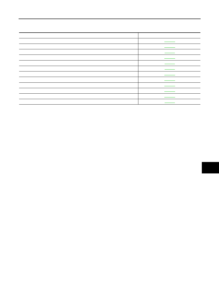
Component Description

INFOID:0000000009950088

Component Reference

BCM

SEC-73

Push-button ignition switch

SEC-48

Door switch

DLK-55

CVT shift selector (detention switch)

SEC-81

Inside key antenna

DLK-44

Remote keyless entry receiver

DLK-75

Stop lamp switch

SEC-46

TCM

SEC-62

Starter relay

SEC-67

Starter control relay

SEC-76

Security indicator lamp

SEC-88

Key warning lamp

DLK-87

SEC-16

< SYSTEM DESCRIPTION >

[WITH INTELLIGENT KEY SYSTEM]

NISSAN VEHICLE IMMOBILIZER SYSTEM-NATS

NISSAN VEHICLE IMMOBILIZER SYSTEM-NATS

System Diagram

INFOID:0000000009950089

System Description

INFOID:0000000009950090

SYSTEM DESCRIPTION

• The NVIS (NATS) is an anti-theft system that registers an Intelligent Key ID to the vehicle and prevents the

engine from being started by an unregistered Intelligent Key. It has higher protection against auto theft
involving the duplication of mechanical keys.

• It performs ID verification when starting the engine in the same way as the Intelligent system, but it performs

the NVIS (NATS) ID verification when inserting the Intelligent Key and performs the Intelligent Key ID verifi-
cation when carrying the Intelligent Key.

• The mechanical key integrated in the Intelligent Key cannot start the engine. When the Intelligent Key bat-

tery is discharged, the NVIS (NATS) ID verification memorized to the transponder integrated with Intelligent
Key backside is contacted to push-button ignition switch. If the verification results are OK, the engine start
operation can be performed by the push-button ignition switch operation.

• Locate the security indicator lamp and apply the anti-theft system equipment sticker that warns that the NVIS

(NATS) is on board the model.

• Security indicator lamp always blinks when the power supply position is in any position except the ON posi-

tion.

• Up to 4 Intelligent Keys can be registered (including the standard ignition key) upon request from the owner.
• When replacing ECM, BCM, or Intelligent Key, the specified procedure (Initialization of BCM and registration

of all Intelligent Keys) using CONSULT is required.

JMKIA7883GB

NISSAN VEHICLE IMMOBILIZER SYSTEM-NATS

SEC-17

< SYSTEM DESCRIPTION >

[WITH INTELLIGENT KEY SYSTEM]

C

D

E

F

G

H

I

J

L

M

A

B

SEC

N

O

P

• Possible symptom of NVIS (NATS) malfunction is “Engine cannot start”. This symptom also occurs because

of other than NVIS(NATS) malfunction, so start the trouble diagnosis according to 

SEC-6, "Work Flow"

.

• If ECM other than genuine part is installed, the engine cannot be started. For ECM replacement procedure,

refer to 

SEC-9, "ECM : Special Repair Requirement"

.

PRECAUTIONS FOR KEY REGISTRATION

• The key registration is a procedure that erases the current NVIS (NATS) ID once, and then reregisters a new

ID operation. Therefore a registered Intelligent Key is necessary for this procedure. Before starting the regis-
tration operation collect all registered Intelligent Keys from the customer.

• When registering the Intelligent Key, perform only one procedure to simultaneously register both ID (NVIS

“NATS” ID and Intelligent Key ID).
The NVIS (NATS) ID registration is the procedure that registers the ID stored into the transponder (inte-
grated in Intelligent Key) to BCM.
The Intelligent key ID registration is the procedure that registers the ID to BCM.

• When performing the Intelligent Key system registration only, the engine cannot be started by Intelligent Key

backside is contacted to push-button ignition switch. When performing the NVIS (NATS) registration only,
the engine cannot be started by the operation when carrying the key. The registrations of both systems
should be performed.

SECURITY INDICATOR LAMP

• Warns that the vehicle is equipped with NVIS (NATS).
• Security indicator lamp always blinks when the ignition switch is in any position except the ON position.
NOTE:
Because security indicator lamp is highly efficient, the battery is barely affected.

ENGINE START OPERATION WHEN INTELLIGENT KEY IS CONTACTED TO PUSH-BUTTON IG-
NITION SWITCH

1.

When brake pedal is depressed while selector lever is in the P position, BCM activates immobilizer
antenna amplifier that is located on push-button ignition switch backside.

2.

When Intelligent Key (transponder built-in) backside is contacted to push-button ignition switch, immobi-
lizer ID verification is started between Intelligent Key built-in transponder and immobilizer antenna ampli-
fier.

3.

When immobilizer ID verification result is OK, buzzer in combination meter sounds.

4.

BCM transmits immobilizer ID verification result to ECM via CAN communication.

5.

BCM turns ACC relay ON and transmits ignition power supply ON signal to IPDM E/R.

6.

IPDM E/R turns ignition relay ON and starts ignition power supply.

7.

BCM detects that the shift position is P or N.

8.

BCM transmits starter request signal to IPDM E/R via CAN communication.
When engine start conditions* are satisfied, BCM turns starter relay in IPDM E/R ON.

9.

When starter request signal is received, IPDM E/R turns starter control relay ON.

10. IPDM E/R supplies power supply via starter relay and starter control relay, activates starter motor, and

starts cranking.

11. When BCM receives engine start or speed feedback signal from ECM, BCM transmits stop signal to IPDM

E/R, turns starter relay OFF, and stops cranking.

POWER SUPPLY POSITION CHANGE TABLE BY PUSH-BUTTON IGNITION SWITCH OPERA-
TION

The power supply position changing operation can be performed with the following operations.
NOTE:
• When an Intelligent Key is within the detection area of inside key antenna and when Intelligent Key backside

is contacted to push-button ignition switch, it is equivalent to the operations below.

• When starting the engine, the BCM monitors under the engine start conditions,
- Brake pedal operating condition
- Selector lever position
- Vehicle speed

Vehicle speed: less than 4 km/h (2.5 MPH)

SEC-18

< SYSTEM DESCRIPTION >

[WITH INTELLIGENT KEY SYSTEM]

NISSAN VEHICLE IMMOBILIZER SYSTEM-NATS

Vehicle speed: 4 km/h (2.5 MPH) or more

Emergency stop operation

• Press and hold the push-button ignition switch for 2 seconds or more.

• Press the push-button ignition switch 3 times or more within 1.5 seconds.

Power supply position

Engine start/stop condition

Push-button ignition switch 

operation frequency

Selector lever

Brake pedal operation condi-

tion

LOCK 

 ACC

Not depressed

1

LOCK 

 ACC 

 ON

Not depressed

2

LOCK 

 ACC 

 ON 

 OFF

Not depressed

3

LOCK 

 START

ACC 

 START

ON 

 START

P or N position

Depressed

1

Engine is running 

 OFF

1

Power supply position

Engine start/stop condition

Push-button ignition switch 

operation frequency

Selector lever

Brake pedal operation condi-

tion

Engine is running 

 ACC 

Emergency stop operation

Engine stall return operation while 
driving 

N position

Not depressed

1


Content   ..  799  800  801  802   ..