Nissan Cube. Manual - part 780
PWO
POWER SOCKET
PWO-5
< REMOVAL AND INSTALLATION >
C
D
E
F
G
H
I
J
K
L
B
A
O
P
N
REMOVAL AND INSTALLATION
POWER SOCKET
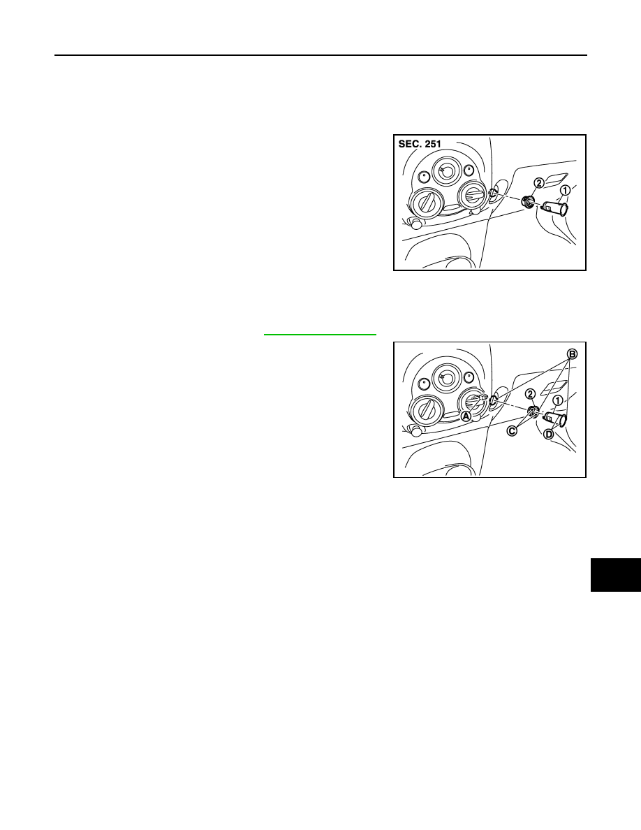
Exploded View
INFOID:0000000009946824
Removal and Installation
INFOID:0000000009946825
REMOVAL
1.
Remove glove box assembly. Refer to
.
2.
Disconnect power socket connector (A).
3.
Pull out inner socket (1) by pushing the ring pawl (C) from the
inner socket hole (square) (D).
4.
Remove ring (2) from instrument panel while pressing pawls.
INSTALLATION
Install in the reverse order of removal.
NOTE:
Align the cut outs of inner socket, ring, and instrument panel.
1
: Inner socket
2
: Ring
JPMIA1472ZZ
B
: Cut out
JPMIA1473ZZ