Nissan Cube. Manual - part 722
PCS
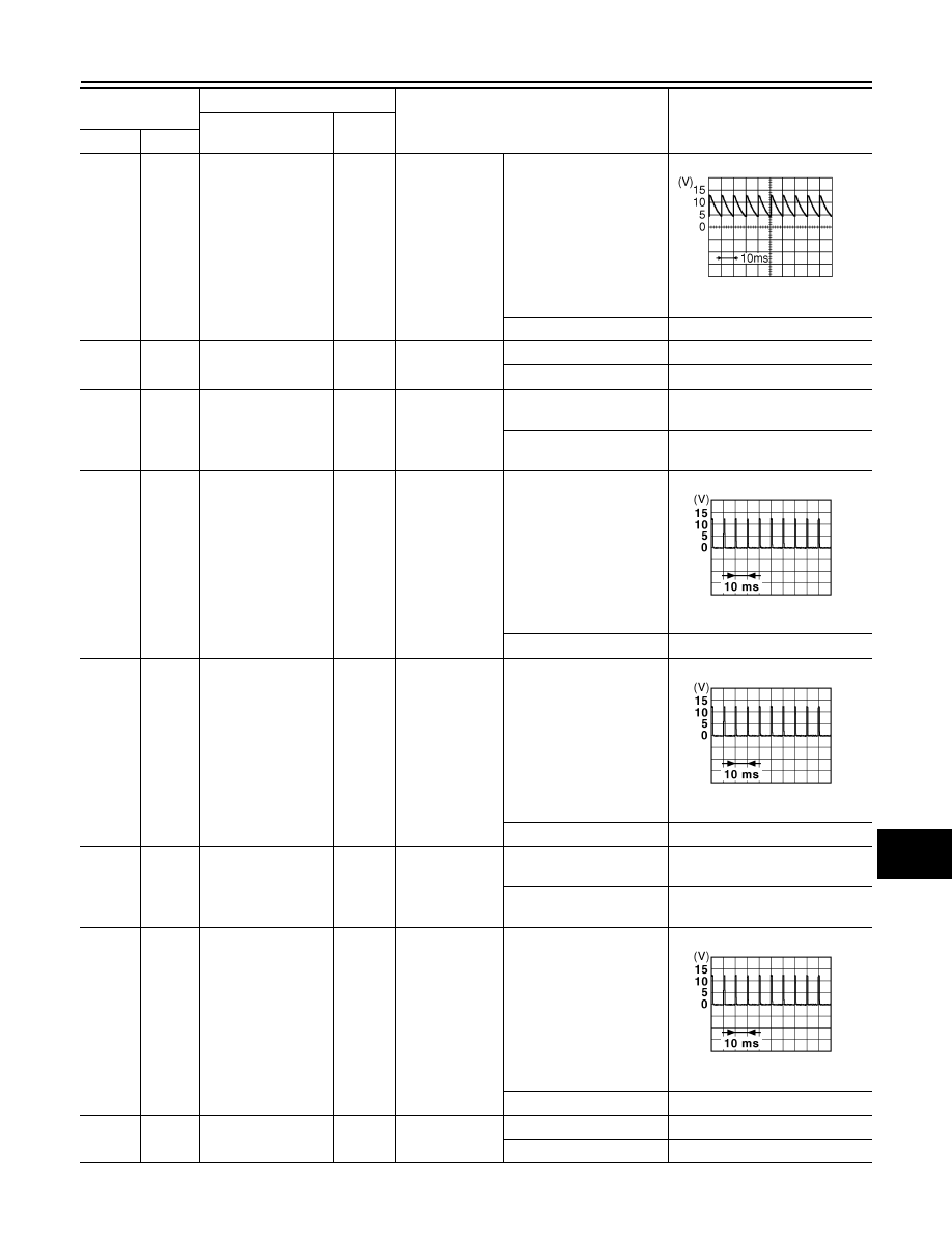
BCM (BODY CONTROL MODULE)
PCS-113
< ECU DIAGNOSIS INFORMATION >
[POWER DISTRIBUTION SYSTEM]
C
D
E
F
G
H
I
J
K
L
B
A
O
P
N
7
(W/R)
Ground
Door key cylinder
switch UNLOCK
Input
Door key cylin-
der switch
NEUTRAL position
8.0 - 8.5 V
UNLOCK position
0 V
8
(W/B)
Ground
Door key cylinder
switch LOCK
Input
Door key cylin-
der switch
NEUTRAL position
12 V
LOCK position
0 V
9
(R)
Ground
Stop lamp switch 1
Input
Stop lamp
switch
OFF (Brake pedal is not
depressed)
0 V
ON (Brake pedal is de-
pressed)
Battery voltage
12
(GR)
Ground
Door lock and unlock
switch LOCK
Input
Door lock and
unlock switch
NEUTRAL position
1.0 - 1.5 V
LOCK position
0 V
13
(BR)
Ground
Door lock and unlock
switch UNLOCK
Input
Door lock and
unlock switch
NEUTRAL position
1.0 - 1.5 V
UNLOCK position
0 V
14
(L/G)
Ground
Optical sensor
Input
Ignition switch
ON
When bright outside of the
vehicle
Close to 5 V
When dark outside of the
vehicle
Close to 0 V
15
(W/L)
Ground
Rear window defog-
ger switch
Input
Rear window
defogger switch
Not pressed
1.0 - 1.5 V
Pressed
0 V
17
(R/G)
Ground
Optical sensor pow-
er supply
Output
Ignition switch
OFF, ACC
0 V
ON
5 V
Terminal No.
(Wire color)
Description
Condition
Value
(Approx.)
Signal name
Input/
Output
+
−
JPMIA0587GB
JPMIA0012GB
JPMIA0012GB
JPMIA0012GB