Index Nissan Nissan Cube (2014 year) - Service and Repair Manual
Search
Content .. 682 683 684 685 ..
Nissan Cube. Manual - part 684
MWI-60
< ECU DIAGNOSIS INFORMATION >
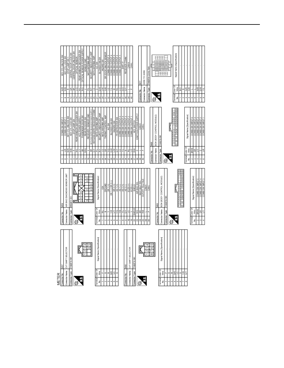
COMBINATION METER
JRNWD0652GB