Nissan Cube. Manual - part 594
HRN-2
< DTC/CIRCUIT DIAGNOSIS >
HORN
DTC/CIRCUIT DIAGNOSIS
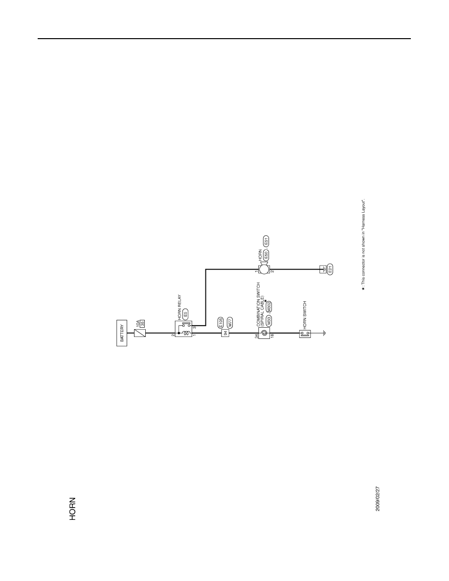
HORN
Wiring Diagram - HORN -
INFOID:0000000009949463
JCLWM3546GB
|
|
|
HRN-2 < DTC/CIRCUIT DIAGNOSIS > HORN DTC/CIRCUIT DIAGNOSIS HORN Wiring Diagram - HORN - INFOID:0000000009949463 JCLWM3546GB |