Nissan Cube. Manual - part 580


  Index      Nissan     Nissan Cube (2014 year) - Service and Repair Manual


Search            


Content   ..  578  579  580  581   ..


Nissan Cube. Manual - part 580


HAC-158

< DTC/CIRCUIT DIAGNOSIS >

[MANUAL AIR CONDITIONING]

MAGNET CLUTCH

MAGNET CLUTCH

Description

INFOID:0000000009951075

• The magnet clutch is the device that drives the compressor with the signal from IPDM E/R. 
• Compressor is driven by the magnet clutch which is charged magnetic force by electrified.
• IPDM E/R controls magnet clutch by turning the built in A/C relay to ON 

 OFF according to ECM request.

Component Function Check

INFOID:0000000009951076

1.

PERFORM AUTO ACTIVE TEST

Perform IPDM E/R auto active test. Refer t

PCS-41, "Diagnosis Description"

.

Does the magnet clutch operate?

YES

>> INSPECTION END

NO

>> Refer to 

HAC-158, "Diagnosis Procedure"

.

Diagnosis Procedure

INFOID:0000000009951077

1.

CHECK MAGNET CLUTCH

1.

Turn the ignition switch OFF.

2.

Disconnect the magnet clutch connector. 

3.

Directly apply the battery voltage to the magnet clutch. Check for operation visually and by sound. 

Does it operate normally?

YES

>> GO TO 2.

NO

>> Replace magnet clutch. Refer to 

HA-33, "MAGNET CLUTCH : Removal and Installation"

.

2.

CHECK MAGNET CLUTCH CIRCUIT CONTINUITY

1.

Turn the ignition switch OFF.

2.

Disconnect the IPDM E/R connector.

3.

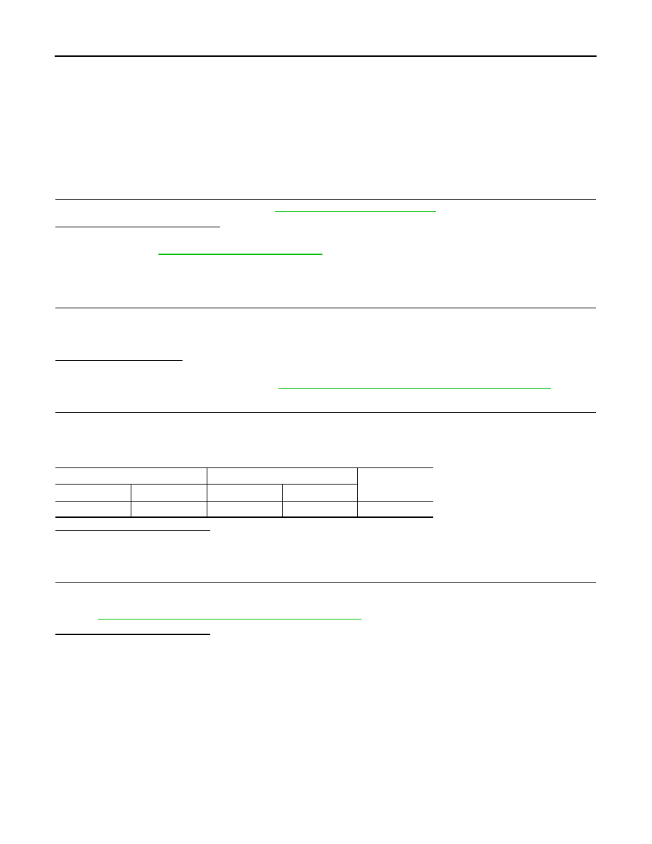
Check continuity between magnet clutch harness connector and IPDM E/R harness connector. 

Is the inspection result normal?

YES

>> GO TO 3.

NO

>> Repair the harnesses and connectors. 

3.

CHECK FUSE

Check 10A fuse (No. 49, located in the IPDM E/R). 
NOTE:
Refer to 

PG-79, "Fuse, Connector and Terminal Arrangement"

Is the inspection result normal?

YES

>> Replace the IPDM E/R. 

NO

>> Replace the fuse after repairing the applicable circuit. 

IPDM E/R

Magnet clutch

Continuity

Connector

Terminal

Connector

Terminal

E15

56

F17

1

Existed

A/C SWITCH

HAC-159

< DTC/CIRCUIT DIAGNOSIS >

[MANUAL AIR CONDITIONING]

C

D

E

F

G

H

J

K

L

M

A

B

HAC

N

O

P

A/C SWITCH

Description

INFOID:0000000009951078

• Each signal is sent to BCM by pressing the A/C switch.
• BCM judges the recognition that A/C switch is ON or OFF according to input switch signal.

Component Function Check

INFOID:0000000009951079

1.

CHECK A/C SWITCH SIGNAL

With CONSULT

1.

Turn the ignition switch ON.

2.

Select the “AIR COND SW” on “DATA MONITOR” in BCM.

3.

Check the A/C switch signal when A/C switch is operated.

Is inspection result normal?

YES

>> INSPECTION END

NO

>> Refer to 

HAC-159, "Diagnosis Procedure"

.

Diagnosis Procedure

INFOID:0000000009951080

1.

CHECK A/C SWITCH SIGNAL OUTPUT

1.

Turn the ignition switch OFF. 

2.

Disconnect the A/C control connector.

3.

Turn the ignition switch ON.

4.

Check output waveform between A/C switch harness connector and the ground with using oscilloscope.

Is inspection result normal?

YES

>> GO TO 2.

NO

>> GO TO 3.

2.

CHECK CONTINUITY A/C CONTROL GROUND CIRCUIT

1.

Turn the ignition switch OFF.

2.

Check continuity between A/C control harness connector and the ground. 

Is inspection result normal?

Monitor item

Condition

Status

AIR COND SW

A/C switch

While pushing

On

While not pushing

Off

(+)

(

)

Output waveform

A/C control

Connector

Terminal

M53

12

Ground

Approx. 1.0

1.5 V

JPMIA0012GB

A/C control

Continuity

Connector

Terminal

M53

15

Ground

Existed

HAC-160

< DTC/CIRCUIT DIAGNOSIS >

[MANUAL AIR CONDITIONING]

A/C SWITCH

YES

>> Replace the A/C switch (A/C control).

NO

>> Repair the harness or connector.

3.

CHECK CONTINUITY BETWEEN A/C CONTROL AND BCM

1.

Turn the ignition switch OFF.

2.

Disconnect the BCM connector.

3.

Check continuity between A/C control harness connector and BCM harness connector.

With Intelligent Key

Without Intelligent Key

Is inspection result normal?

YES

>> GO TO 4.

NO

>> Repair the harness or connector.

4.

CHECK CONTINUITY BETWEEN A/C CONTROL AND GROUND

Check continuity between A/C control harness connector and the ground.

Is inspection result normal?

YES

>> Replace the BCM. Refer to 

BCS-155, "Exploded View"

.

NO

>> Repair the harness or connector.

A/C control

BCM

Continuity

Connector

Terminal

Connector

Terminal

M53

12

M68

27

Existed

A/C control

BCM

Continuity

Connector

Terminal

Connector

Terminal

M53

12

M65

27

Existed

A/C control

Continuity

Connector

Terminal

M53

12

Ground

Not existed

DEFROSTER POSITION SIGNAL

HAC-161

< DTC/CIRCUIT DIAGNOSIS >

[MANUAL AIR CONDITIONING]

C

D

E

F

G

H

J

K

L

M

A

B

HAC

N

O

P

DEFROSTER POSITION SIGNAL

Description

INFOID:0000000009951081

• Each signal is sent to BCM by setting the D/F or DEF position.
• BCM judges the change of the air inlet and recognition of A/C switch ON or OFF according to input switch

signal.

Component Function Check

INFOID:0000000009951082

1.

CHECK DEFROSTER POSITION SIGNAL

With CONSULT

1.

Turn the ignition switch ON.

2.

Select the “FR DEF SW” on “DATA MONITOR” in BCM.

3.

Check the A/C switch signal when A/C switch is operated.

Is inspection result normal?

YES

>> INSPECTION END

NO

>> Refer to 

HAC-161, "Diagnosis Procedure"

.

Diagnosis Procedure

INFOID:0000000009951083

1.

CHECK VOLTAGE BETWEEN A/C CONTROL AND GROUND

1.

Turn the ignition switch OFF.

2.

Disconnect the A/C control connector.

3.

Turn the ignition switch ON.

4.

Check voltage between A/C control harness connector and the ground.

Is inspection result normal?

YES

>> Replace the A/C control.

NO

>> GO TO 2.

2.

CHECK CONTINUITY BETWEEN A/C CONTROL AND BCM

1.

Turn the ignition switch OFF.

2.

Disconnect the BCM connector.

3.

Check continuity between A/C control harness connector and BCM harness connector.

With Intelligent Key

Without Intelligent Key

Is inspection result normal?

Monitor item

Condition

Status

FR DEF SW

MODE position

D/F or DEF

On

VENT, B/L or FOOT

Off

(+)

(

)

Voltage

(Approx.)

A/C control

Connector

Terminal

M53

6

Ground

12 V

A/C control

BCM

Continuity

Connector

Terminal

Connector

Terminal

M53

6

M71

103

Existed

A/C control

BCM

Continuity

Connector

Terminal

Connector

Terminal

M53

6

M66

31

Existed


Content   ..  578  579  580  581   ..