Nissan Cube. Manual - part 579


  Index      Nissan     Nissan Cube (2014 year) - Service and Repair Manual


Search            


Content   ..  577  578  579  580   ..


Nissan Cube. Manual - part 579


HAC-154

< DTC/CIRCUIT DIAGNOSIS >

[MANUAL AIR CONDITIONING]

BLOWER MOTOR

BLOWER MOTOR

Description

INFOID:0000000009951072

COMPONENT DESCRIPTION
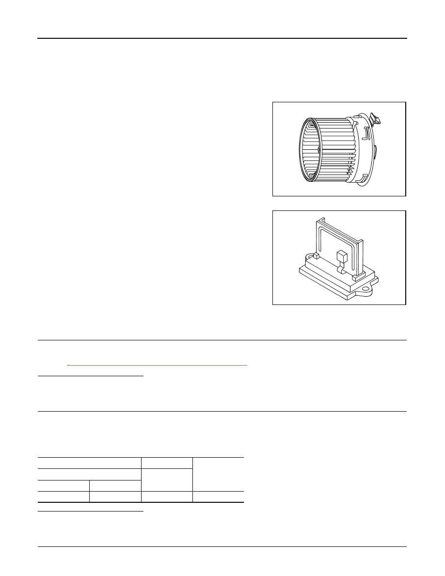
Blower Motor

• The blower motor is installed in the RH side of A/C unit assembly.
• The blower motor adopts the forcible air cooling system and one-

touch installation system without any screws.

Blower Fan Resistor

• Compact and lightweight resistor is adopted with outstanding venti-

lation. 

• Temperature fuse is installed to protects the blower motor circuit.

Diagnosis Procedure

INFOID:0000000009951073

1.

CHECK FUSE

Check 15A fuses [Nos. 15 and 17, located in the fuse block (J/B)].
NOTE:
Refer to 

PG-77, "Fuse, Connector and Terminal Arrangement"

.

Is the inspection result normal?

YES

>> GO TO 2.

NO

>> Replace fuse after repairing the applicable circuit.

2.

CHECK POWER SUPPLY FOR BLOWER MOTOR

1.

Turn the ignition switch OFF.

2.

Disconnect the blower motor connector.

3.

Turn the ignition switch ON.

4.

Check voltage between blower motor harness connector and the ground.

Is the inspection result normal?

YES

>> GO TO 3.

NO

>> GO TO 4.

3.

CHECK BLOWER RELAY

JPIIA1575ZZ

ZJIA0545J

(+)

(

)

Voltage

(Approx.)

Blower motor

Connector

Terminal

M39

1

Ground

Battery voltage

BLOWER MOTOR

HAC-155

< DTC/CIRCUIT DIAGNOSIS >

[MANUAL AIR CONDITIONING]

C

D

E

F

G

H

J

K

L

M

A

B

HAC

N

O

P

1.

Turn the ignition switch OFF.

2.

Perform the component inspection of blower motor relay. Refer to 

HAC-156, "Component Inspection"

.

Is the inspection result normal?

YES

>> Replace the harness or connector between blower motor and fuse.

NO

>> Replace the blower relay.

4.

CHECK FAN SWITCH GROUND CIRCUIT

1.

Turn the ignition switch OFF.

2.

Disconnect the fan switch connector.

3.

Check continuity between fan switch harness connector and the ground.

Is the inspection result normal?

YES

>> GO TO 5.

NO

>> Repair the harness or connector.

5.

CHECK CONTINUITY BETWEEN FAN SWITCH AND BLOWER MOTOR

Check continuity fan switch harness connector and blower motor harness connector.

Is the inspection result normal?

YES

>> GO TO 6.

NO

>> Repair the harness or connector.

6.

CHECK VOLTAGE BETWEEN BLOWER FAN RESISTOR AND GROUND

1.

Disconnect the blower fan resistor connector.

2.

Turn the ignition switch ON.

3.

Check voltage between blower fan resistor harness connector and the ground.

Is the inspection result normal?

YES

>> GO TO 7.

NO

>> Repair the harness or connector between blower fan resistor and blower motor.

7.

CHECK BLOWER FAN RESISTOR

1.

Turn the ignition switch OFF.

2.

Perform the component inspection of blower fan resistor. Refer to 

HAC-156, "Component Inspection"

.

Is the inspection result normal?

YES

>> GO TO 8.

NO

>> Replace the blower fan resistor.

8.

CHECK CIRCUIT CONTINUITY BETWEEN FAN SWITCH AND BLOWER FAN RESISTOR

Check continuity between fan switch harness connector and blower fan resistor.

Fan switch

Continuity

Connector

Terminal

M73

3

Ground

Existed

Fan switch

Blower motor

Continuity

Connector

Terminal

Connector

Terminal

M73

5

M39

2

Existed

(+)

(

)

Voltage

(Approx.)

Blower fan resistor

Connector

Terminal

M306

3

Ground

12 V

HAC-156

< DTC/CIRCUIT DIAGNOSIS >

[MANUAL AIR CONDITIONING]

BLOWER MOTOR

Is the inspection result normal?

YES

>> GO TO 9.

NO

>> Repair the harness or connector.

9.

CHECK FAN SWITCH

Perform the component inspection of fan switch. Refer to 

HAC-156, "Component Inspection"

.

Is the inspection result normal?

YES

>> Replace the blower motor.

NO

>> Replace the fan switch (A/C control).

Component Inspection

INFOID:0000000009951074

BLOWER MOTOR

1.

CHECK BLOWER MOTOR

1.

Remove the blower motor. Refer to 

VTL-13, "Exploded View"

2.

Check that there is not any mixing foreign object in the blower motor. 

Is the inspection result normal?

YES

>> GO TO 2.

NO

>> Replace the blower motor.

2.

CHECK BLOWER MOTOR

Check that there is not breakage or damage in the blower motor. 

Is the inspection result normal?

YES

>> GO TO 3.

NO

>> Replace the blower motor.

3.

CHECK BLOWER MOTOR

Check that the blower motor turns smoothly. 

Is the inspection result normal?

YES

>> INSPECTION END

NO

>> Replace the blower motor.

BLOWER MOTOR RELAY

1.

CHECK BLOWER MOTOR

1.

Remove the blower motor relay. Refer to 

PG-77, "Fuse, Connector and Terminal Arrangement"

2.

Check the continuity between the blower motor relay terminal 3
and 5 when the voltage is supplied between terminal 1 and 2. 

Is the inspection result normal?

YES

>> INSPECTION END

NO

>> Replace the blower motor relay.

BLOWER FAN RESISTOR

Fan switch

Blower fan resistor

Continuity

Connector

Terminal

Connector

Terminal

M73

4

M306

4

Existed

1

1

2

2

Blower motor relay

Voltage

Continuity

Terminal

3

5

ON

Existed

OFF

Not existed

JSIIA1551ZZ

BLOWER MOTOR

HAC-157

< DTC/CIRCUIT DIAGNOSIS >

[MANUAL AIR CONDITIONING]

C

D

E

F

G

H

J

K

L

M

A

B

HAC

N

O

P

1.

CHECK BLOWER MOTOR

1.

Turn the ignition switch OFF. 

2.

Disconnect the blower fan resistor connector.

3.

Check the resistance between blower fan resistor terminals. Refer to the applicable table for the normal
value.

Is the inspection result normal?

YES

>> INSPECTION END

NO

>> Replace the blower fan resistor.

FAN SWITCH

1.

CHECK FAN SWITCH

1.

Turn the ignition switch OFF. 

2.

Disconnect the fan switch connector.

3.

Check the fan switch circuit continuity.

Is the inspection result normal?

YES

>> INSPECTION END

NO

>> Replace the fan switch (A/C control).

Blower fan resistor

Resistance: 

(Approx.)

Terminal

3

4

0.43

1

1.03

2

3

Fan switch

Condition

Continuity

Terminal

Dial position

3

2

1st

Existed

1

2nd

4

3rd

5

4th


Content   ..  577  578  579  580   ..