Nissan Cube. Manual - part 569


  Index      Nissan     Nissan Cube (2014 year) - Service and Repair Manual


Search            


Content   ..  567  568  569  570   ..


Nissan Cube. Manual - part 569


HAC-114

< SYMPTOM DIAGNOSIS >

[AUTOMATIC AIR CONDITIONING]

AUTOMATIC AIR CONDITIONING SYSTEM

SYMPTOM DIAGNOSIS

AUTOMATIC AIR CONDITIONING SYSTEM

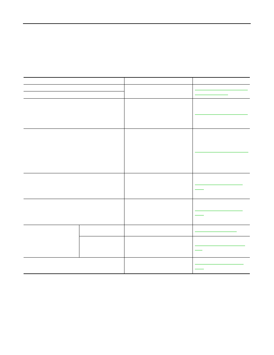
Diagnosis Chart By Symptom

INFOID:0000000009951023

CAUTION:

Perform the self-diagnoses with on board diagnosis and CONSULT before performing the symptom
diagnosis. If any malfunction result or DTC is detected, perform the corresponding diagnosis.

Symptom

Corresponding malfunction part

Check item/Reference

A/C system does not activate.

• Power supply circuit of A/C system
• A/C control (built-in A/C auto amp.)

HAC-64, "A/C AUTO AMP. : Di-
agnosis Procedure"

A/C system cannot be controlled.

Blower motor operation is malfunctioning.

• Blower  motor
• Power supply system of blower mo-

tor

• The circuit between blower motor 

and A/C auto amp.

• A/C auto amp.

HAC-54, "Diagnosis Procedure"


Magnet clutch does not operate. 

• Magnet clutch
• The circuit between magnet clutch 

and IPDM E/R

• IPDM E/R (A/C relay)
• The circuit between ECM and refrig-

erant pressure sensor

• Refrigerant pressure sensor
• CAN communication line
• A/C auto amp.

HAC-59, "Diagnosis Procedure"

• Insufficient cooling
• No cool air comes out. (Air flow volume is normal.)

• Magnet clutch control system
• Drive belt slipping
• Cooler cycle
• Air leakage from each duct
• Temperature setting trimmer

HAC-115, "Diagnosis Proce-
dure"

• Insufficient heating
• No warm air comes out. (Air flow volume is normal.)

• Engine cooling system
• Heater hose
• Heater core
• Air leakage from each duct
• Temperature setting trimmer

HAC-117, "Diagnosis Proce-
dure"

Noise is heard when the A/C 
system operates.

During compressor op-
eration

Cooler cycle 

HA-10, "Symptom Table"

During blower motor op-
eration

• Mixing any foreign object in blower 

motor

• Blower motor fan breakage
• Blower motor rotation inferiority

HAC-57, "Component Inspec-
tion"

• Memory function dose not operates.
• Setting temperature dose not memorize.

• Power supply system of A/C auto 

amp.

• A/C auto amp.

HAC-120, "Inspection Proce-
dure"

INSUFFICIENT COOLING

HAC-115

< SYMPTOM DIAGNOSIS >

[AUTOMATIC AIR CONDITIONING]

C

D

E

F

G

H

J

K

L

M

A

B

HAC

N

O

P

INSUFFICIENT COOLING

Description

INFOID:0000000009951024

Symptom

• Insufficient cooling
• No cool air comes out. (Air flow volume is normal.)

Diagnosis Procedure

INFOID:0000000009951025

CAUTION:

Perform the self-diagnoses with on board diagnosis and CONSULT before performing symptom diag-
nosis. If any malfunction result or DTC is detected, perform the corresponding diagnosis.

1.

CHECK MAGNET CLUTCH OPERATION

1.

Turn the ignition switch ON.

2.

Operate the fan control switch.

3.

Press the A/C switch.

4.

Check that the indicator of the A/C switch turns ON. Check visually and by sound that the compressor
operates.

5.

Press the A/C switch again.

6.

Check that the indicator of the A/C switch turns OFF. Check that the compressor stops.

Is the inspection result normal?

YES

>> GO TO 2.

NO

>> Perform the diagnosis of “COMPRESSOR DOSE NOT OPERATE” in “SYMPTOM DIAGNOSIS”.

Refer to 

HAC-118, "Diagnosis Procedure"

.

2.

CHECK DRIVE BELT

Check tension of the drive belt. Refer to 

EM-13, "Checking"

.

Is the inspection result normal?

YES

>> GO TO 3.

NO

>> Adjust or replace drive belt depending on the inspection results.

3.

CHECK REFRIGERANT CYCLE PRESSURE

Connect the recovery/recycling recharging equipment to the vehicle and perform the pressure inspection with
the gauge. Refer to 

HA-8, "Symptom Table"

.

Is the inspection result normal?

YES

>> GO TO 4.

NO

>> Repair or replace the parts depending on the inspection results.

4.

CHECK AIR LEAKAGE FROM EACH DUCT

Check duct and nozzle, etc. of the air conditioner system for leakage.
Is the inspection result normal?

YES

>> GO TO 5.

NO

>> Repair or replace parts depending on the inspection results.

5.

CHECK AMBIENT TEMPERATURE DISPLAY

Check that there is not much difference between actual ambient temperature and indicated temperature on
information display in combination meter. 
NOTE:
Actual ambient temperature is sensor recognition temperature of on board self-diagnosis STEP-5.

Is the inspection result normal?

YES

>> GO TO 6.

NO

>> Perform the diagnosis for the A/C auto amp. connection recognition signal. Refer to 

MWI-47,

"Diagnosis Procedure"

.

6.

CHECK SETTING OF TEMPERATURE SETTING TRIMMER

1.

Check the setting value of temperature setting trimmer. Refer to 

HAC-10, "Temperature Setting Trimmer"

HAC-116

< SYMPTOM DIAGNOSIS >

[AUTOMATIC AIR CONDITIONING]

INSUFFICIENT COOLING

2.

Check that the temperature setting trimmer is set to “+ direction”. 
NOTE:
The control temperature can be set with the setting of the temperature setting trimmer.

3.

Set the difference between the set temperature and control temperature to “0”.

Is inspection result normal?

YES

>> INSPECTION END

NO

>> Replace the A/C auto amp.

INSUFFICIENT HEATING

HAC-117

< SYMPTOM DIAGNOSIS >

[AUTOMATIC AIR CONDITIONING]

C

D

E

F

G

H

J

K

L

M

A

B

HAC

N

O

P

INSUFFICIENT HEATING

Description

INFOID:0000000009951026

Symptom

• Insufficient heating
• No warm air comes out. (Air flow volume is normal.)

Diagnosis Procedure

INFOID:0000000009951027

CAUTION:

Perform the self-diagnoses with on board diagnosis and CONSULT before performing symptom diag-
nosis. If any malfunction result or DTC is detected, perform the corresponding diagnosis.

1.

CHECK COOLING SYSTEM

1.

Check the engine coolant level and check for leakage. Refer to 

CO-8, "Inspection"

.

2.

Check the radiator cap. Refer to 

CO-12, "RADIATOR CAP : Inspection"

.

3.

Check the water flow sounds of the engine coolant. Refer to 

CO-9, "Refilling"

.

Is the inspection result normal?

YES

>> GO TO 2.

NO

>> Refill the engine coolant and repair or replace the parts depending on the inspection results.

2.

CHECK HEATER HOSE

Check the installation of heater hose by visually or touching.

Is the inspection result normal?

YES

>> GO TO 3.

NO

>> Repair or replace parts depending on the inspection results.

3.

CHECK HEATER CORE

1.

Check the temperature of inlet hose and outlet hose of heater core.

2.

Check that the inlet side of heater core is hot and the outlet side is slightly lower than/almost equal to the
inlet side.

CAUTION:

Always perform the temperature inspection in a short period of time because the engine coolant
temperature is very hot.

Is the inspection result normal?

YES

>> GO TO 4.

NO

>> Replace the heater core. Refer to 

HA-42, "Exploded View (Automatic Air Conditioner)"

.

4.

CHECK AIR LEAKAGE FROM EACH DUCT

Check duct and nozzle, etc. of the air conditioner system for air leakage.

Is the inspection result normal?

YES

>> GO TO 5.

NO

>> Repair or replace parts depending on the inspection results.

5.

CHECK SETTING OF TEMPERATURE SETTING TRIMMER

1.

Check the setting value of temperature setting trimmer. Refer to 

HAC-10, "Temperature Setting Trimmer"

2.

Check that the temperature setting trimmer is set to “

 direction”. 

NOTE:
The control temperature can be set by the temperature setting trimmer.

3.

Set the difference between the set temperature and control temperature to “0”.

Are the symptoms solved?

YES

>> INSPECTION END

NO

>> Replace the A/C auto amp.


Content   ..  567  568  569  570   ..