Nissan Cube. Manual - part 553
HAC-50
< DTC/CIRCUIT DIAGNOSIS >
[AUTOMATIC AIR CONDITIONING]
INTAKE DOOR MOTOR
INTAKE DOOR MOTOR
Description
INFOID:0000000009950997
COMPONENT DESCRIPTION
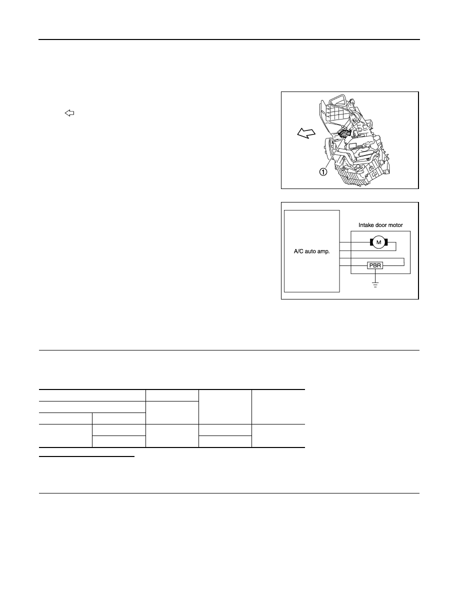
• The intake door motor (1) is installed to A/C unit assembly.
• The A/C auto amp. sends the control signal to Intake door motor.
When intake door motor receives the control signal, intake door is
moved to appropriate position by PBR (Potentio Balance Resistor)
opening angle indication signal.
Intake door motor circuit
Diagnosis Procedure
INFOID:0000000009950998
POWER SUPPLY CIRCUIT
1.
CHECK INTAKE DOOR MOTOR DRIVE SIGNAL
1.
Turn the ignition switch ON.
2.
Check voltage between intake door motor harness connector and the ground when intake switch is oper-
ated.
Is inspection result normal?
YES
>> GO TO 4.
NO
>> GO TO 2.
2.
CHECK CONTINUITY BETWEEN A/C AUTO AMP. AND INTAKE DOOR MOTOR
1.
Turn the ignition switch OFF.
2.
Disconnect the A/C auto amp. connector.
3.
Disconnect the intake door motor connector.
4.
Check continuity between A/C auto amp. harness connector and intake door motor harness connector.
: Vehicle front
JPIIA1741ZZ
JPIIA1656GB
(+)
(
−
)
Condition
Voltage
(Approx.)
Intake door motor
—
Connector
Terminal
M54
5
Ground
FRE
→
REC
12 V
6
REC
→
FRE