Nissan Cube. Manual - part 540
EXPANSION VALVE
HA-49
< REMOVAL AND INSTALLATION >
C
D
E
F
G
H
J
K
L
M
A
B
HA
N
O
P
EXPANSION VALVE
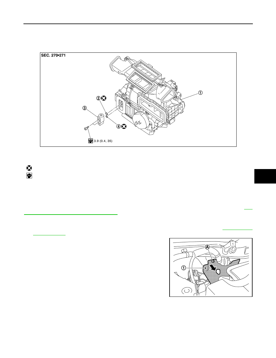
Exploded View
INFOID:0000000009950365
Removal and Installation
INFOID:0000000009950366
CAUTION:
Perform lubricant return operation before each refrigeration system disassembly. However, if a large
amount of refrigerant or lubricant is detected, never perform lubricant return operation. Refer to
26, "Perform Lubricant Return Operation"
REMOVAL
1.
Use a refrigerant collecting equipment (for HFC-134a) to discharge the refrigerant. Refer to
2.
Remove mounting nut (A), and lower dash insulator (1) to a
position without the hindrance for work.
3.
Remove the mounting bolt and nut installed in low-pressure flexible hose from the vehicle.
1.
A/C unit assembly
2.
O-ring
3.
Expansion valve
4.
O-ring
: Always replace after every disassembly.
: N·m (kg-m, in-lb)
JPIIA1697GB
JPIIA1702ZZ