Nissan Cube. Manual - part 539
A/C UNIT ASSEMBLY
HA-45
< REMOVAL AND INSTALLATION >
C
D
E
F
G
H
J
K
L
M
A
B
HA
N
O
P
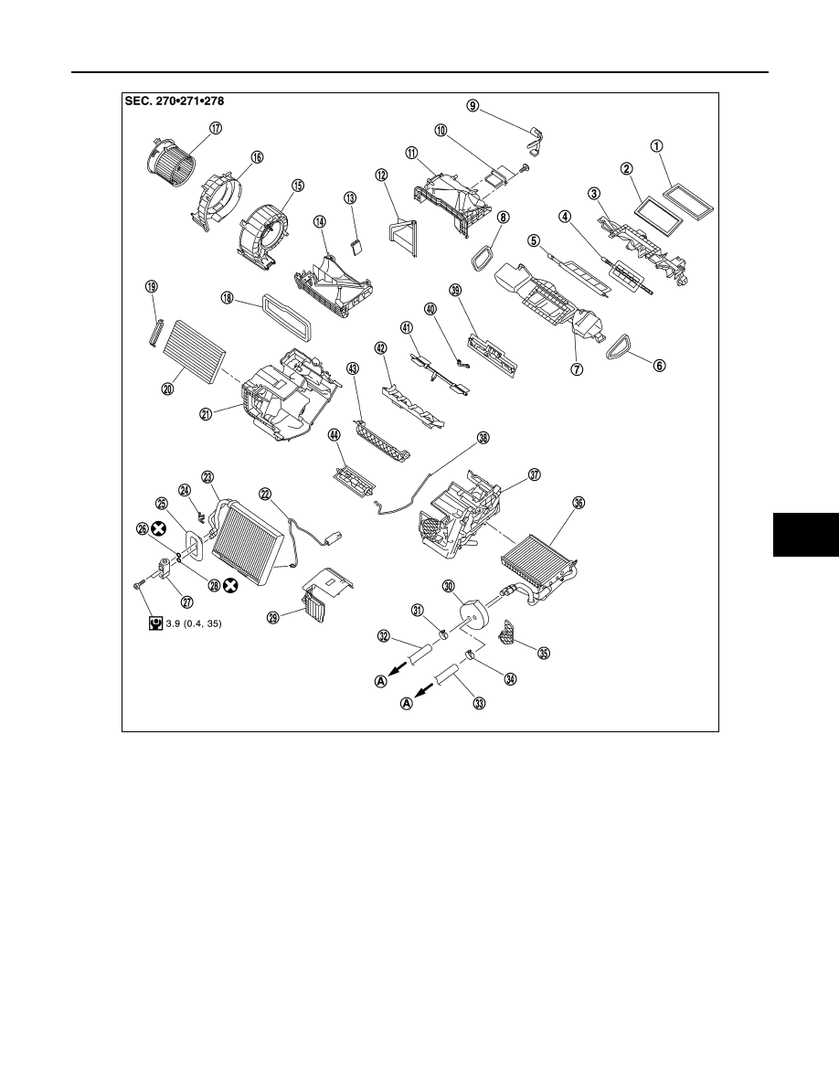
1.
Ventilator seal
2.
Defroster seal
3.
Upper attachment case
4.
Sub defroster door
5.
Center ventilator and defroster door 6.
Side ventilator seal LH
7.
Lower attachment case
8.
Side ventilator seal RH
9.
Sub harness
10. Blower fan resistor
11.
Upper intake case
12. Intake door
13. Sub intake door
14.
Lower intake case
15. Blower case LH
16. Blower case RH
17.
Blower motor
18. Intake seal
19. Filter cover
20.
In-cabin microfilter
21. A/C unit case RH
22. Thermo control amp.
23.
Evaporator
24. Plate
25. Expansion valve grommet
26.
O-ring
27. Expansion valve
28. O-ring
29.
Evaporator cover
30. Heater pipe grommet
31. Clamp
32.
Heater hose
33. Heater hose
34. Clamp
35.
Heater pipe support
36. Heater core
37. A/C unit case LH
38.
Case packing
39. Foot door
40. Foot door rod
41.
Side ventilator door
42. Air mix door guide
43. Upper air mix door
44.
Lower air mix door
A.
To water outlet
JPIIA1696GB