Nissan Cube. Manual - part 422


  Index      Nissan     Nissan Cube (2014 year) - Service and Repair Manual


Search            


Content   ..  420  421  422  423   ..


Nissan Cube. Manual - part 422


EM-92

< UNIT DISASSEMBLY AND ASSEMBLY >

CYLINDER BLOCK

a.

Using snap ring pliers, install new snap ring to the groove of the piston rear side. 
• Insert it fully into groove to install. 

b.

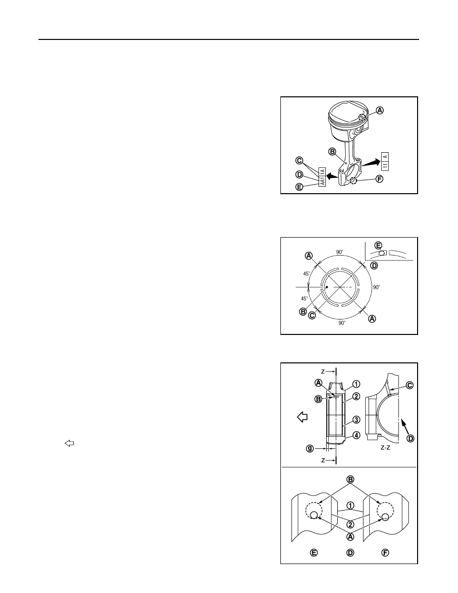
Assemble piston to connecting rod.
• Using an industrial use drier or similar tool, heat the piston until the piston pin can be pushed in by hand

without excess force [approximately 60 to 70

°

C (140 to 158

°

F)]. From the front to the rear, insert piston

pin into piston and connecting rod.

• Assemble so that the front mark (A) on the piston head and

the oil hole (B) and the cylinder number (C) on connecting rod
are positioned as shown in the figure.

c.

Install new snap ring to the groove of the piston front side. 
• Insert it fully into groove to install. 
• After installing, check that connecting rod moves smoothly.

8.

Using a piston ring expander (commercial service tool), install
piston rings. 

CAUTION:

• Be careful not to damage piston.
• Be careful not to damage piston rings by expanding them excessively.
• Position each ring with the gap as shown in the figure referring

to the piston front mark.

CAUTION:

Never contact the rail end gap under the oil ring with the
oil drain cast groove of piston.

• Install second ring with the stamped surface facing upward.

9.

Install connecting rod bearing upper (2) and lower (3) to con-
necting rod (1) and connecting rod cap (4).

• Install the connecting rod in the dimension shown in the figure. 
• Check that connecting rod bearing oil hole (A) is completely in

the inside of connecting rod oil hole chamfered area (B).

• When installing connecting rod bearings, apply new engine oil

to the bearing surface (inside). Do not apply new engine oil to
the back surface, but thoroughly clean it. 
NOTE:
• There is no positioning tab.
• Install the connecting rod bearings in the center of connect-

ing rod and connecting rod cap as shown in the figure. For
service operation, the center position can be checked, visu-
ally.

D

: Big end diameter grade

E

: Small end diameter grade

F

: Front mark (connecting rod)

A

: Oil ring upper or lower rail gap

B

: Front mark

C

: Second ring and oil ring spacer gap

D

: Top ring gap

E

: Stamped mark

PBIC3241J

PBIC3242J

C

: Oil hole (connecting rod)

D

:  View  D

E

:  OK

F

:  NG

g

: 2.55 - 2.95 mm (0.1004 - 0.1161 in)

: Engine front

JPBIA2155ZZ

CYLINDER BLOCK

EM-93

< UNIT DISASSEMBLY AND ASSEMBLY >

C

D

E

F

G

H

I

J

K

L

M

A

EM

N

P

O

10. Install piston and connecting rod assembly to crankshaft. 

• Position crankshaft pin corresponding to connecting rod to be installed onto the bottom dead center. 
• Apply new engine oil sufficiently to the cylinder bore, piston and crankshaft pin. 
• Match the cylinder position with the cylinder number (C) on

connecting rod to install. 

• Install so that front mark (A) on the piston head faces the front

of engine.

• Using a piston ring compressor [SST: EM03470000 (J-8037)]

(A) or suitable tool, install piston with the front mark on the pis-
ton head facing the front of the engine. 

CAUTION:

Be careful not to damage the cylinder wall and crankshaft
pin, resulting from an interference of the connecting rod
big end.

11. Install connecting rod cap. 

• Match the stamped cylinder number marks (C) on connecting

rod with those on connecting rod cap to install.   

12. Tighten connecting rod cap bolt with the following procedure:

CAUTION:

• Check that there is no gap in the thrust surface (A) of the

joint between connecting rod (1) and connecting rod cap
(2) and that these parts are in the correct position. And
then, tighten the connecting rod cap bolts.

• If the connecting rod cap bolts are reused, measure the

outer diameter. Refer to 

EM-95, "Inspection"

.

a.

Apply new engine oil to the threads and seats of connecting rod
cap bolts. 

b.

Tighten connecting rod cap bolts.

c.

Completely loosen connecting rod cap bolts.

d.

Tighten connecting rod cap bolts.

B

: Oil hole

D

: Big end diameter grade

E

: Small end diameter grade

F

: Front mark (connecting rod)

PBIC3241J

PBIC3244J

A

: Front mark (piston)

B

: Oil hole

D

: Big end diameter grade

E

: Small end diameter grade

F

: Front mark (connecting rod)

PBIC3241J

: 27.5 N·m (2.8 kg-m, 20 ft-lb)

: 0 N·m (0 kg-m, 0 ft-lb)

PBIC3510J

EM-94

< UNIT DISASSEMBLY AND ASSEMBLY >

CYLINDER BLOCK

e.

Then turn all connecting rod cap bolts 60 degrees clockwise (angle tightening).

CAUTION:

Check and confirm the tightening angle by using an angle
wrench [SST: KV10112100 (BT8653-A)] (A) or protractor.
Never judge by visual inspection without the tool.

• After tightening connecting rod cap bolt, check that crankshaft rotates smoothly. 
• Check the connecting rod side clearance. Refer to 

EM-95, "Inspection"

.

13. Install oil pan (upper). Refer to 

EM-82, "Exploded View"

.

NOTE:
Install the rear oil seal after installing the oil pan (upper).

14. Install rear oil seal. Refer to 

EM-63, "REAR OIL SEAL : Removal and Installation"

.

15. Install flywheel (M/T models) or drive plate (CVT models).

Drive plate (CVT models)

• Secure crankshaft with a stopper plate [SST: KV11105210 (J-

44716)], (A) and tighten mounting bolts crosswise over several
times.

• Install pilot converter (1), drive plate (2), and reinforcement

plate (3) as shown in the figure.

• Using a drift of 33 mm (1.30 in) in dia meter, press-fit pilot con-

verter into the end of crankshaft until it stops.

Fly wheel (M/T models)

• Secure crankshaft with a stopper plate [SST: KV11105210 (J-44716)] and tighten mounting bolts cross-

wise over several times.
NOTE:
M/T models have no pilot bushing and reinforcement plate.

16. Install knock sensor.

: 19.6 N·m (2.0 kg-m, 14 ft-lb)

PBIC3245J

1

: Drive plate

PBIC3226J

A

: Crankshaft rear end

B

:  R

PBIC4075E

CYLINDER BLOCK

EM-95

< UNIT DISASSEMBLY AND ASSEMBLY >

C

D

E

F

G

H

I

J

K

L

M

A

EM

N

P

O

• Install knock sensor (1) with harness connector facing toward

the rear of engine. 

CAUTION:

• Never tighten mounting bolts while holding the harness

connector.   

• If any impact by dropping is applied to knock sensor,

replace it with a new one.

NOTE:
• Check that there is no foreign material on the cylinder block mating surface and the back surface of

knock sensor. 

• Check that knock sensor does not interfere with other parts.

17. Install crankshaft position sensor (POS) and crankshaft position sensor (POS) cover.

CAUTION:

• Do not reuse O-ring.
• Handle crankshaft position sensor (POS) carefully and avoid impacts.
• Never disassemble.
• Never place crankshaft position sensor (POS) in a location where it is exposed to magnetism.

18. Install oil filter (for intake valve timing control) (1) in the direction

shown in the figure.
• Check that the oil filter (for intake valve timing control) does

not protrude from the upper surface of cylinder block (2) after
installation.

19. Assemble in the reverse order of disassembly.

Inspection

INFOID:0000000009944969

CRANKSHAFT END PLAY

• Measure the clearance between thrust bearings and crankshaft

arm when crankshaft is moved fully forward or backward with a dial
indicator (A).

• If the measured value exceeds the limit, replace thrust bearings,

and measure again. If it still exceeds the limit, replace crankshaft
also.

CONNECTING ROD SIDE CLEARANCE

A

: Cylinder block left side

: Engine front

PBIC3246J

PBIC3260J

Standard and Limit

: Refer to 

EM-118, "Cylinder 

Block"

.

PBIC3252J


Content   ..  420  421  422  423   ..