Nissan Cube. Manual - part 370


  Index      Nissan     Nissan Cube (2014 year) - Service and Repair Manual


Search            


Content   ..  368  369  370  371   ..


Nissan Cube. Manual - part 370


EC-366

< DTC/CIRCUIT DIAGNOSIS >

[MR18DE]

P1805 BRAKE SWITCH

• Harness connectors E105, M77
• 10 A fuse (No. 9)
• Harness for open or short between stop lamp switch and battery

>> Repair open circuit or short to ground or short to power in harness or connectors.

4.

CHECK STOP LAMP SWITCH INPUT SIGNAL CIRCUIT FOR OPEN AND SHORT

1.

Disconnect ECM harness connector.

2.

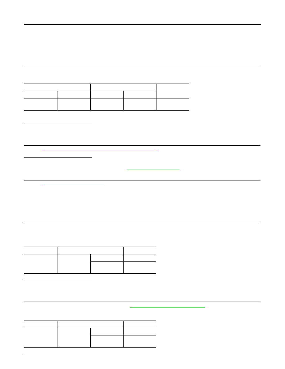
Check the continuity between ECM harness connector and stop lamp switch harness connector.

3.

Also check harness for short to ground and short to power.

Is the inspection result normal?

YES

>> GO TO 5.

NO

>> Repair open circuit or short to ground or short to power in harness or connectors.

5.

CHECK STOP LAMP SWITCH

Refer to 

EC-366, "Component Inspection (Stop Lamp Switch)"

.

Is the inspection result normal?

YES

>> GO TO 6.

NO

>> Replace stop lamp switch. Refer to 

BR-17, "Exploded View"

.

6.

CHECK INTERMITTENT INCIDENT

Refer to 

GI-40, "Intermittent Incident"

.

>> INSPECTION END

Component Inspection (Stop Lamp Switch)

INFOID:0000000009947495

1.

CHECK STOP LAMP SWITCH-I

1.

Turn ignition switch OFF.

2.

Disconnect stop lamp switch harness connector.

3.

Check the continuity between stop lamp switch terminals under the following conditions.

Is the inspection result normal?

YES

>> INSPECTION END

NO

>> GO TO 2.

2.

CHECK STOP LAMP SWITCH-II

1.

Adjust stop lamp switch installation. Refer to 

BR-7, "Inspection and Adjustment"

.

2.

Check the continuity between stop lamp switch terminals under the following conditions.

Is the inspection result normal?

ECM

Stop lamp switch

Continuity

Connector

Terminal

Connector

Terminal

E16

99

E114 (M/T)

E115 (CVT)

2

Existed

Terminals

Condition

Continuity

1 and 2

Brake pedal

Fully released

Not existed

Slightly de-
pressed

Existed

Terminals

Condition

Continuity

1 and 2

Brake pedal

Fully released

Not existed

Slightly de-
pressed

Existed

P1805 BRAKE SWITCH

EC-367

< DTC/CIRCUIT DIAGNOSIS >

[MR18DE]

C

D

E

F

G

H

I

J

K

L

M

A

EC

N

P

O

YES

>> INSPECTION END

NO

>> Replace stop lamp switch. Refer to 

BR-17, "Exploded View"

.

EC-368

< DTC/CIRCUIT DIAGNOSIS >

[MR18DE]

P2096, P2097 A/F SENSOR 1

P2096, P2097 A/F SENSOR 1

Description

INFOID:0000000009947496

The air fuel ratio (A/F) sensor 1 is a planar one-cell limit current sen-
sor. The sensor element of the A/F sensor 1 is composed an elec-
trode layer, which transports ions. It has a heater in the element.
The sensor is capable of precise measurement   = 1, but also in the
lean and rich range. Together with its control electronics, the sensor
outputs a clear, continuous signal throughout a wide   range.
The exhaust gas components diffuse through the diffusion layer at
the sensor cell. An electrode layer is applied voltage, and this current
relative oxygen density in lean. Also this current relative hydrocar-
bon density in rich.

Therefore, the A/F sensor 1 is able to indicate air fuel ratio by this
electrode layer of current. In addition, a heater is integrated in the
sensor to ensure the required operating temperature of about 800

°

C

(1,472

°

F).

DTC Logic

INFOID:0000000009947497

DTC DETECTION LOGIC

To judge the malfunction, the A/F signal computed by ECM from the A/F sensor 1 signal is monitored not to be
shifted to LEAN side or RICH side.

DTC CONFIRMATION PROCEDURE

1.

PRECONDITIONING

If DTC Confirmation Procedure has been previously conducted, always turn ignition switch OFF and wait at
least 10 seconds before conducting the next test.
TESTING CONDITION:
Before performing the following procedure, confirm that battery voltage is more than 11 V at idle.

>> GO TO 2.

2.

PERFORM DTC CONFIRMATION PROCEDURE

1.

Clear the mixture ratio self-learning value. Refer to 

EC-22, "MIXTURE RATIO SELF-LEARNING VALUE

CLEAR : Special Repair Requirement"

.

2.

Turn ignition switch OFF and wait at least 10 seconds.

3.

Start engine and keep the engine speed between 3,500 and 4,000 rpm for 1 minute under no load.

4.

Let engine idle for 1 minute.

JMBIA0112GB

PBIB3354E

DTC No.

CONSULT screen terms

(Trouble diagnosis content)

DTC detecting condition

Possible Cause

P2096

POST CAT FUEL TRIM SYS B1
(Post catalyst fuel trim system 
too lean bank 1)

The output voltage computed by ECM from the 
A/F sensor 1 signal is shifts to the lean side for a 
specified period.

• A/F sensor 1
• A/F sensor 1 heater
• Heated oxygen sensor 2
• Fuel pressure
• Fuel injector
• Intake air leaks
• Exhaust gas leaks

P2097

POST CAT FUEL TRIM SYS B1
(Post catalyst fuel trim system 
too rich bank 1)

The A/F signal computed by ECM from the A/F 
sensor 1 signal is shifts to the rich side for a spec-
ified period.

P2096, P2097 A/F SENSOR 1

EC-369

< DTC/CIRCUIT DIAGNOSIS >

[MR18DE]

C

D

E

F

G

H

I

J

K

L

M

A

EC

N

P

O

5.

Keep engine speed between 2,500 and 3,000 rpm for 20 minutes.

6.

Check 1st trip DTC.

Is 1st trip DTC detected?

YES

>> Go to 

EC-369, "Diagnosis Procedure"

.

NO

>> INSPECTION END

Diagnosis Procedure

INFOID:0000000009947498

1.

CHECK GROUND CONNECTION

1.

Turn ignition switch OFF.

2.

Check ground connection E38. Refer to 

GI-43, "Circuit Inspection"

.

Is the inspection result normal?

YES

>> GO TO 2.

NO

>> Repair or replace ground connection.

2.

CHECK HARNESS CONNECTOR

1.

Disconnect A/F sensor 1 harness connector.

2.

Check harness connector for water. 

Is the inspection result normal?

YES

>> GO TO 3.

NO

>> Repair or replace harness connector.

3.

RETIGHTEN A/F SENSOR 1 AND HEATED OXYGEN SENSOR 2

1.

Loosen and retighten the A/F sensor 1 and heated oxygen sensor 2. Refer to 

EM-29, "Exploded View"

 or

EX-5, "Exploded View"

.

>> GO TO 4.

4.

CHECK FOR EXHAUST GAS LEAK

1.

Start engine and run it at idle.

2.

Listen for an exhaust gas leak before the three way catalyst 2.

Is exhaust gas leak detected?

YES

>> Repair or replace malfunctioning parts.

NO

>> GO TO 5.

5.

CHECK FOR INTAKE AIR LEAK

1.

Reconnect A/F sensor 1 harness connector.

2.

Start engine and run it at idle.

3.

Listen for an intake air leak after the mass air flow sensor.

Is intake air leak detected?

YES

>> Repair or replace.

NO

>> GO TO 6.

6.

CLEAR THE MIXTURE RATIO SELF-LEARNING VALUE

1.

Clear the mixture ratio self-learning value. Refer to 

EC-22, "MIXTURE RATIO SELF-LEARNING VALUE

CLEAR : Special Repair Requirement"

.

2.

Run engine for at least 10 minutes at idle speed.

Is the 1st trip DTC P0171 or P0172 detected? Is it difficult to start engine?

YES

>> Perform trouble diagnosis for DTC P0171or P0172. Refer to 

EC-215, "DTC Logic"

 or 

EC-219,

"DTC Logic"

.

NO

>> GO TO 7.

7.

CHECK A/F SENSOR 1 POWER SUPPLY CIRCUIT

1.

Disconnect A/F sensor 1 harness connector.

2.

Turn ignition switch ON.

Water should not exit.


Content   ..  368  369  370  371   ..