Nissan Cube. Manual - part 366


  Index      Nissan     Nissan Cube (2014 year) - Service and Repair Manual


Search            


Content   ..  364  365  366  367   ..


Nissan Cube. Manual - part 366


EC-350

< DTC/CIRCUIT DIAGNOSIS >

[MR18DE]

P1554 BATTERY CURRENT SENSOR

2.

Also check harness for short to ground and short to power.

Is the inspection result normal?

YES

>> GO TO 10.

NO

>> Repair open circuit, short to ground or short to power in harness or connectors.

10.

CHECK BATTERY CURRENT SENSOR

Refer to 

EC-350, "Component Inspection"

.

Is the inspection result normal?

YES

>> GO TO 11.

NO

>> Replace battery negative cable assembly.

11.

CHECK INTERMITTENT INCIDENT

Refer to 

GI-40, "Intermittent Incident"

.

>> INSPECTION END

Component Inspection

INFOID:0000000009947475
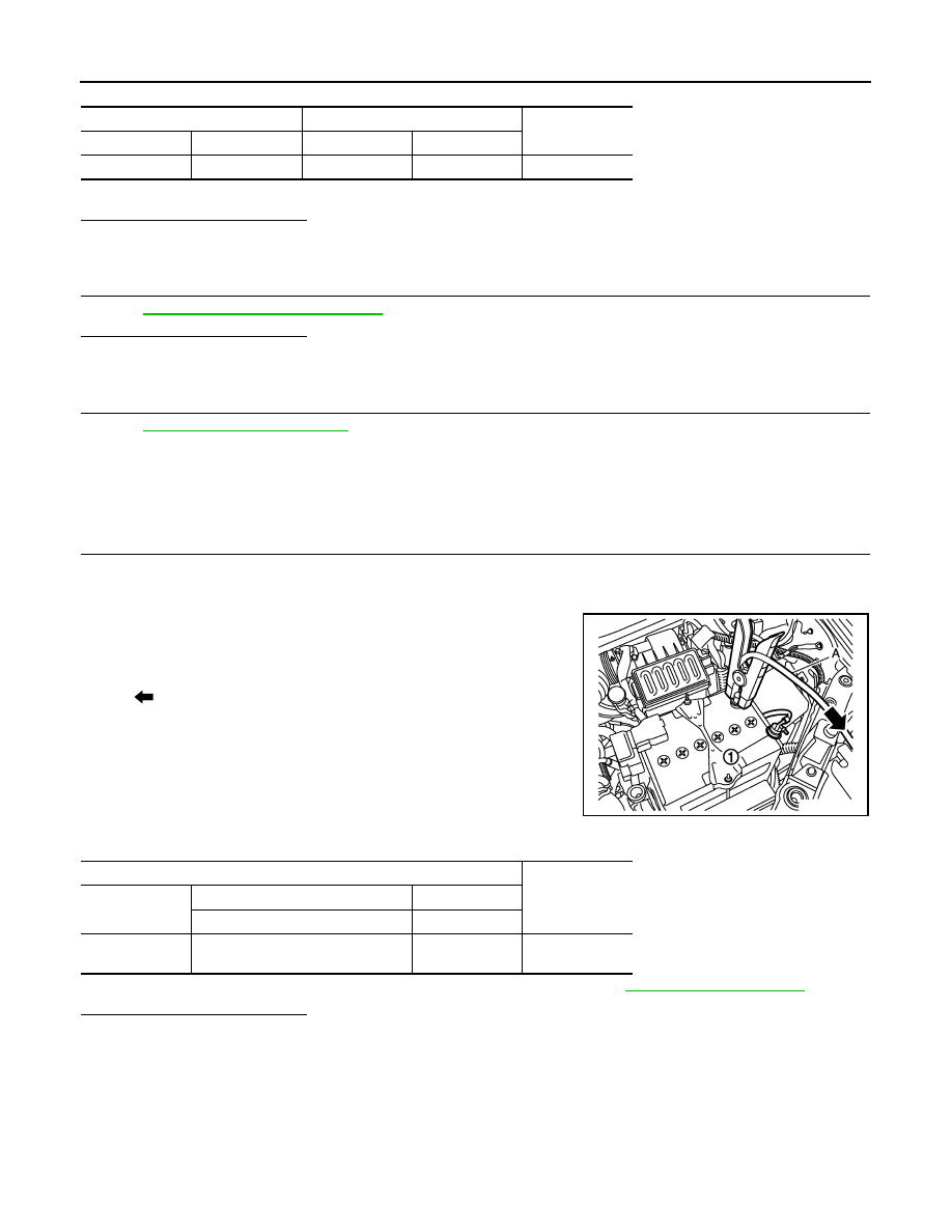
1.

CHECK BATTERY CURRENT SENSOR

1.

Turn ignition switch OFF.

2.

Reconnect harness connectors disconnected.

3.

Disconnect battery negative cable.

4.

Install jumper cable (A) between battery negative terminal and
body ground.

5.

Turn ignition switch ON.

6.

Check the voltage between ECM harness connector and
ground.

Before measuring the terminal voltage, confirm that the battery is fully charged. Refer to 

PG-3, "How to Handle Battery"

.

Is the inspection result normal?

YES

>> INSPECTION END

NO

>> Replace battery negative cable assembly.

Battery current sensor

ECM

Continuity

Connector

Terminal

Connector

Terminal

F53

3

F8

57

Existed

1

: Battery negative terminal

: To body ground

JMBIA2313ZZ

ECM

Voltage

Connector

+

-

Terminal

Terminal

F8

57

(Battery current sensor signal)

64

Approx. 2.5 V

P1564 ASCD STEERING SWITCH

EC-351

< DTC/CIRCUIT DIAGNOSIS >

[MR18DE]

C

D

E

F

G

H

I

J

K

L

M

A

EC

N

P

O

P1564 ASCD STEERING SWITCH

Description

INFOID:0000000009947476

ASCD steering switch has variant values of electrical resistance for each button. ECM reads voltage variation
of switch, and determines which button is operated.
Refer to 

EC-65, "System Description"

 for the ASCD function.

DTC Logic

INFOID:0000000009947477

DTC DETECTION LOGIC

NOTE:
If DTC P1564 is displayed with DTC P0605, first perform the trouble diagnosis for DTC P0605. Refer to

EC-312, "DTC Logic"

.

DTC CONFIRMATION PROCEDURE

1.

PRECONDITIONING

If DTC Confirmation Procedure has been previously conducted, always turn ignition switch OFF and wait at
least 10 seconds before conducting the next test. 

>> GO TO 2.

2.

PERFORM DTC CONFIRMATION PROCEDURE

1.

Turn ignition switch ON.

2.

Wait at least 10 seconds.

3.

Press MAIN switch for at least 10 seconds, then release it and wait at least 10 seconds.

4.

Press CANCEL switch for at least 10 seconds, then release it and wait at least 10 seconds.

5.

Press RESUME/ACCELERATE switch for at least 10 seconds, then release it and wait at least 10 sec-
onds.

6.

Press SET/COAST switch for at least 10 seconds, then release it and wait at least 10 seconds.

7.

Check DTC.

Is DTC detected?

YES

>> Go to 

EC-351, "Diagnosis Procedure"

.

NO

>> INSPECTION END

Diagnosis Procedure

INFOID:0000000009947478

1.

CHECK GROUND CONNECTION

1.

Turn ignition switch OFF.

2.

Check ground connection E38. Refer to Ground Inspection in 

GI-43, "Circuit Inspection"

Is the inspection result normal?

YES

>> GO TO 2.

NO

>> Repair or replace ground connection.

2.

CHECK ASCD STEERING SWITCH CIRCUIT

 With CONSULT

1.

Turn ignition switch ON.

DTC No.

Trouble diagnosis 

name

DTC detecting condition

Possible cause

P1564

ASCD steering switch

• An excessively high voltage signal from the 

ASCD steering switch is sent to ECM.

• ECM detects that input signal from the 

ASCD steering switch is out of the specified 
range.

• ECM detects that the ASCD steering switch 

is stuck ON.

• Harness or connectors

(The switch circuit is open or shorted.)

• ASCD steering switch
• ECM

EC-352

< DTC/CIRCUIT DIAGNOSIS >

[MR18DE]

P1564 ASCD STEERING SWITCH

2.

Select “MAIN SW”, “CANCEL SW”, “RESUME/ACC SW” and “SET SW” in “DATA MONITOR” mode with
CONSULT.

3.

Check each item indication under the following conditions.

 Without CONSULT

1.

Turn ignition switch ON.

2.

Check the voltage between ECM harness connector terminals.

Is the inspection result normal?

YES

>> GO TO 8.

NO

>> GO TO 3.

3.

CHECK ASCD STEERING SWITCH GROUND CIRCUIT FOR OPEN AND SHORT

1.

Turn ignition switch OFF.

2.

Disconnect ECM harness connector.

3.

Disconnect combination switch harness connector M352.

4.

Check the continuity between combination switch and ECM harness connector.

5.

Also check harness for short to ground and short to power.

Is the inspection result normal?

YES

>> GO TO 5.

NO

>> GO TO 4.

4.

DETECT MALFUNCTIONING PART

Check the following.
• Harness connectors M77, E105
• Combination switch (spiral cable)
• Harness for open and short between ECM and combination switch

Monitor item

Condition

Indication

MAIN SW

MAIN switch

Pressed

ON

Released

OFF

CANCEL SW

CANCEL switch

Pressed

ON

Released

OFF

RESUME/ACC 
SW

RESUME/ACCELERATE switch

Pressed

ON

Released

OFF

SET SW

SET/COAST switch

Pressed

ON

Released

OFF

ECM

Condition

Voltage

Connector

+

-

Terminal

Terminal

E16

94

(ASCD steering 

switch signal)

95

MAIN switch: Pressed

Approx. 0V

CANCEL switch: Pressed

Approx. 1V

SET/COAST switch: Pressed

Approx. 2V

RESUME/ACCELERATE switch: 
Pressed

Approx. 3V

All ASCD steering switches: Re-
leased

Approx. 4V

Combination 

switch

ECM

Continuity

Terminal

Connector

Terminal

16

E16

95

Existed

P1564 ASCD STEERING SWITCH

EC-353

< DTC/CIRCUIT DIAGNOSIS >

[MR18DE]

C

D

E

F

G

H

I

J

K

L

M

A

EC

N

P

O

>> Repair open circuit or short to ground or short to power in harness or connectors.

5.

CHECK ASCD STEERING SWITCH INPUT SIGNAL CIRCUIT FOR OPEN AND SHORT

1.

Check the continuity between ECM harness connector and combination switch.

2.

Also check harness for short to ground and short to power.

Is the inspection result normal?

YES

>> GO TO 7.

NO

>> GO TO 6.

6.

DETECT MALFUNCTIONING PART

Check the following.
• Harness connectors M77, E105
• Combination switch (spiral cable)
• Harness for open and short between ECM and combination switch

>> Repair open circuit or short to ground or short to power in harness or connectors.

7.

CHECK ASCD STEERING SWITCH

Refer to 

EC-353, "Component Inspection"

.

Is the inspection result normal?

YES

>> GO TO 8.

NO

>> Replace ASCD steering switch. Refer to 

ST-9, "Exploded View"

.

8.

CHECK INTERMITTENT INCIDENT

Refer to 

GI-40, "Intermittent Incident"

.

>> INSPECTION END

Component Inspection

INFOID:0000000009947479

1.

CHECK ASCD STEERING SWITCH

1.

Disconnect combination switch (spiral cable) harness connector.

2.

Check the continuity between combination switch harness connector terminals under following conditions.

Is the inspection result normal?

YES

>> INSPECTION END

NO

>> Replace ASCD steering switch. Refer to 

ST-9, "Exploded View"

.

combination 

switch

ECM

Continuity

Terminal

Connector

Terminal

13

E16

94

Existed

Combination switch

Condition

Resistance

Connector

Terminals

M302

13 and 16

MAIN switch: Pressed

Approx. 0 

CANCEL switch: Pressed

Approx. 250 

SET/COAST switch: Pressed

Approx. 660 

RESUME/ACCELERATE switch: 
Pressed

Approx. 1,480 

All ASCD steering switches: Re-
leased

Approx. 4,000 


Content   ..  364  365  366  367   ..