Nissan Cube. Manual - part 358
EC-318
< DTC/CIRCUIT DIAGNOSIS >
[MR18DE]
P0850 PNP SWITCH
4.
Check 1st trip DTC.
Is 1st trip DTC detected?
YES
>> Go to
NO
>> INSPECTION END
5.
PERFORM COMPONENT FUNCTION CHECK
Perform component function check. Refer to
EC-318, "Component Function Check"
NOTE:
Use component function check the overall function of the transmission range switch circuit (CVT models) or
the park/neutral position (PNP) switch circuit (M/T models). During this check, a 1st trip DTC might not be con-
firmed.
Is the inspection result normal?
YES
>> INSPECTION END
NO
>> Go to
Component Function Check
INFOID:0000000009947440
1.
PERFORM COMPONENT FUNCTION CHECK
1.
Turn ignition switch ON.
2.
Check the voltage between ECM harness connector and ground under the following conditions.
Is the inspection result normal?
YES
>> INSPECTION END
NO
>> Go to
Diagnosis Procedure
INFOID:0000000009947441
1.
CHECK TRANSMISSION RANGE SWITCH (CVT) OR PNP SWITCH (M/T) POWER SUPPLY CIRCUIT
1.
Turn ignition switch OFF.
2.
Disconnect transmission range switch (CVT) or park/neutral position (PNP) switch (M/T) harness connec-
tor.
3.
Turn ignition switch ON.
4.
Check the voltage between transmission range switch (CVT) or PNP switch (M/T) harness connector and
ground.
CVT models
ENG SPEED
1,200 - 6,375 rpm
COOLAN TEMP/S
More than 70
°
C (158
°
F)
B/FUEL SCHDL
2.5 - 31.8 msec
VHCL SPEED SE
More than 64 km/h (40 mph)
Selector lever
Suitable position
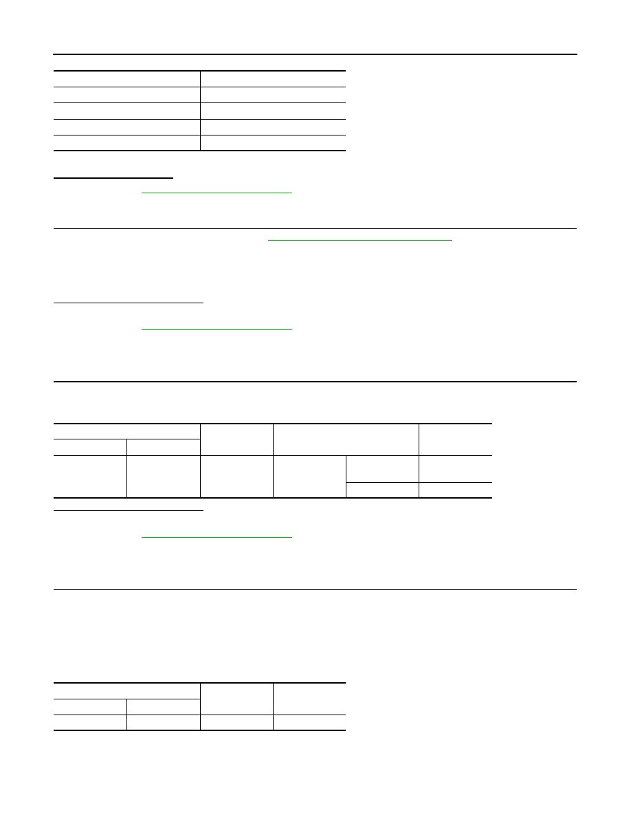
ECM
Ground
Condition
Voltage
Connector
Terminal
F7
14
(PNP signal)
Ground
Selector lever
P or N (CVT)
Neutral (M/T)
Approx. 0 V
Except above
Battery voltage
Transmission range switch
Ground
Voltage
Connector
Terminal
F21
1
Ground
Battery voltage