Nissan Cube. Manual - part 289
EC-42
< SYSTEM DESCRIPTION >
[MR18DE]
MULTIPORT FUEL INJECTION SYSTEM
MULTIPORT FUEL INJECTION SYSTEM
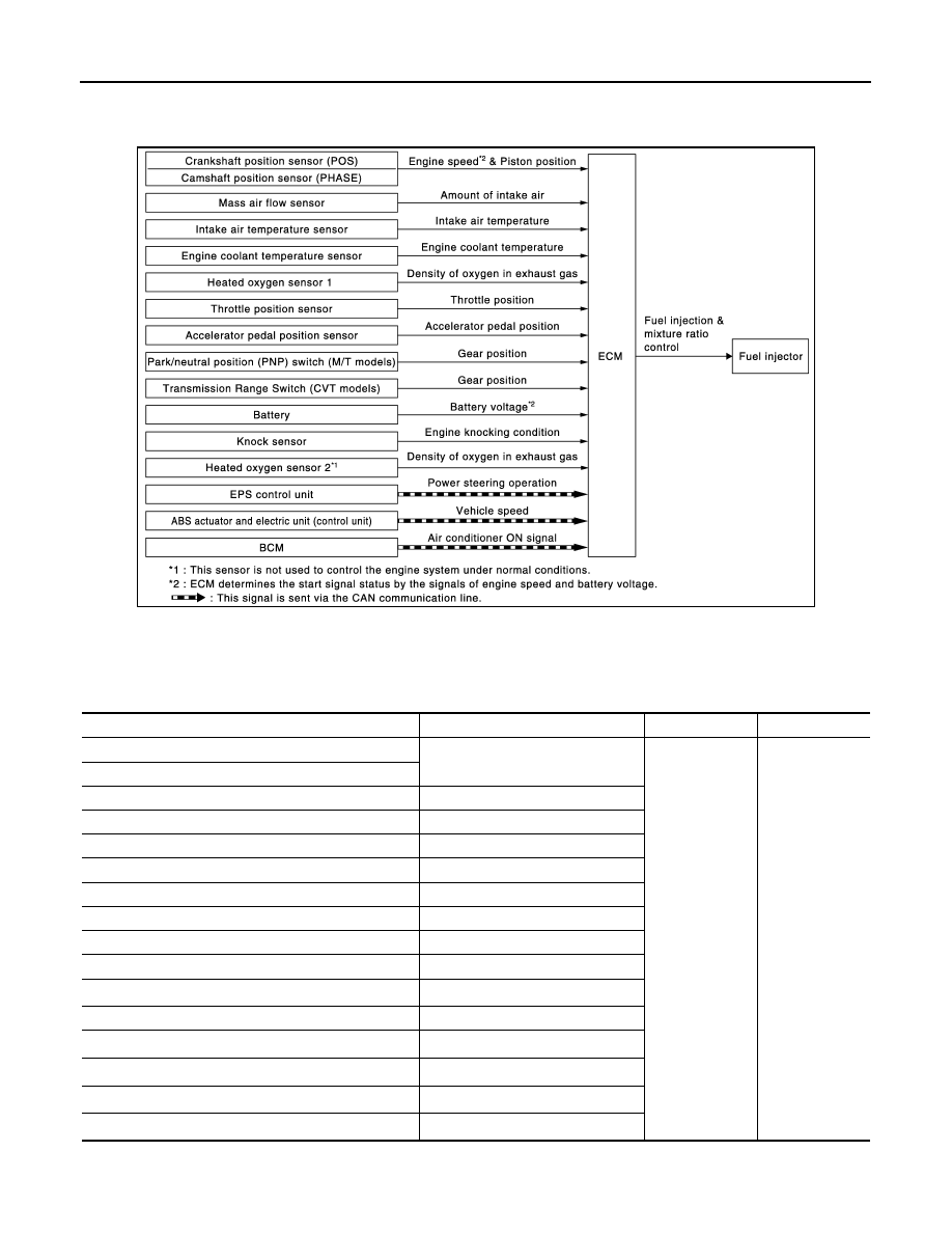
System Diagram
INFOID:0000000009947198
System Description
INFOID:0000000009947199
INPUT/OUTPUT SIGNAL CHART
*1: This sensor is not used to control the engine system under normal conditions.
*2: This signal is sent to the ECM via the CAN communication line.
JMBIA2931GB
Sensor
Input signal to ECM
ECM function
Actuator
Crankshaft position sensor (POS)
Engine speed*
3
Piston position
Fuel injection &
mixture ratio
control
Fuel injector
Camshaft position sensor (PHASE)
Mass air flow sensor
Amount of intake air
Intake air temperature sensor
Intake air temperature
Engine coolant temperature sensor
Engine coolant temperature
Air fuel ratio (A/F) sensor 1
Density of oxygen in exhaust gas
Throttle position sensor
Throttle position
Accelerator pedal position sensor
Accelerator pedal position
Park/neutral position (PNP) switch (M/T models)
Gear position
Transmission range switch (CVT models)
Gear position
Battery
Battery voltage*
3
Knock sensor
Engine knocking condition
Heated oxygen sensor 2*
1
Density of oxygen in exhaust gas
EPS control unit
Power steering operation*
2
ABS actuator and electric unit (control unit)
Vehicle speed*
2
BCM
Air conditioner ON signal*
2