Nissan Cube. Manual - part 199
DLK-62
< DTC/CIRCUIT DIAGNOSIS >
[WITH INTELLIGENT KEY SYSTEM]
DOOR LOCK AND UNLOCK SWITCH
NO
>> GO TO 2.
2.
CHECK DOOR LOCK AND UNLOCK SWITCH CIRCUIT
1.
Disconnect BCM connector and power window main switch connector.
2.
Check continuity between BCM harness connector and front power window switch (passenger side) har-
ness connector.
3.
Check continuity between BCM connector and ground.
Is the inspection result normal?
YES
>> GO TO 3.
NO
>> Repair or replace harness.
3.
CHECK BCM OUTPUT SIGNAL
1.
Connect BCM connector.
2.
Check signal between BCM harness connector and ground using oscilloscope.
Is the inspection result normal?
YES
>> GO TO 6.
NO
>> Replace BCM. Refer to
BCS-88, "Removal and Installation"
4.
CHECK DOOR LOCK AND UNLOCK SWITCH GROUND
Check continuity between front power window switch (passenger side) harness connector and ground.
Is the inspection result normal?
YES
>> GO TO 5.
NO
>> Repair or replace harness.
5.
CHECK DOOR LOCK AND UNLOCK SWITCH
Check front power window switch (passenger side).
Refer to
DLK-63, "PASSENGER SIDE : Component Inspection"
.
BCM
Front power window switch (passenger side)
Continuity
Connector
Terminal
Connector
Terminal
M66
12
D25
1
Existed
13
2
BCM
Ground
Continuity
Connector
Terminal
M66
12
Not existed
13
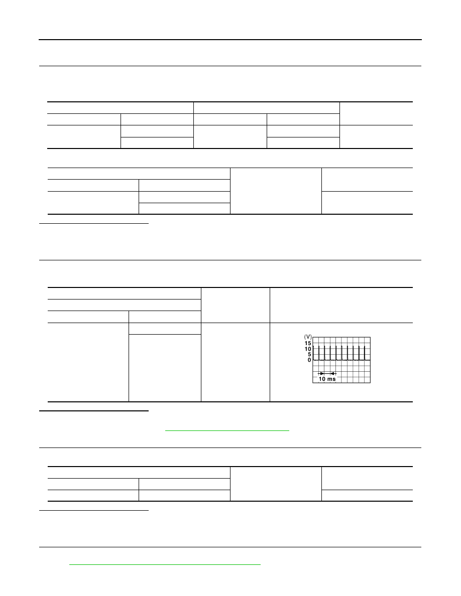
(+)
(–)
Signal
(Reference value)
BCM
Connector
Terminal
M66
12
Ground
1.0 - 1.5 V
13
JPMIA0012GB
Front power window switch (passenger side)
Ground
Continuity
Connector
Terminal
M25
3
Existed