Nissan Cube. Manual - part 198
DLK-58
< DTC/CIRCUIT DIAGNOSIS >
[WITH INTELLIGENT KEY SYSTEM]
DOOR SWITCH
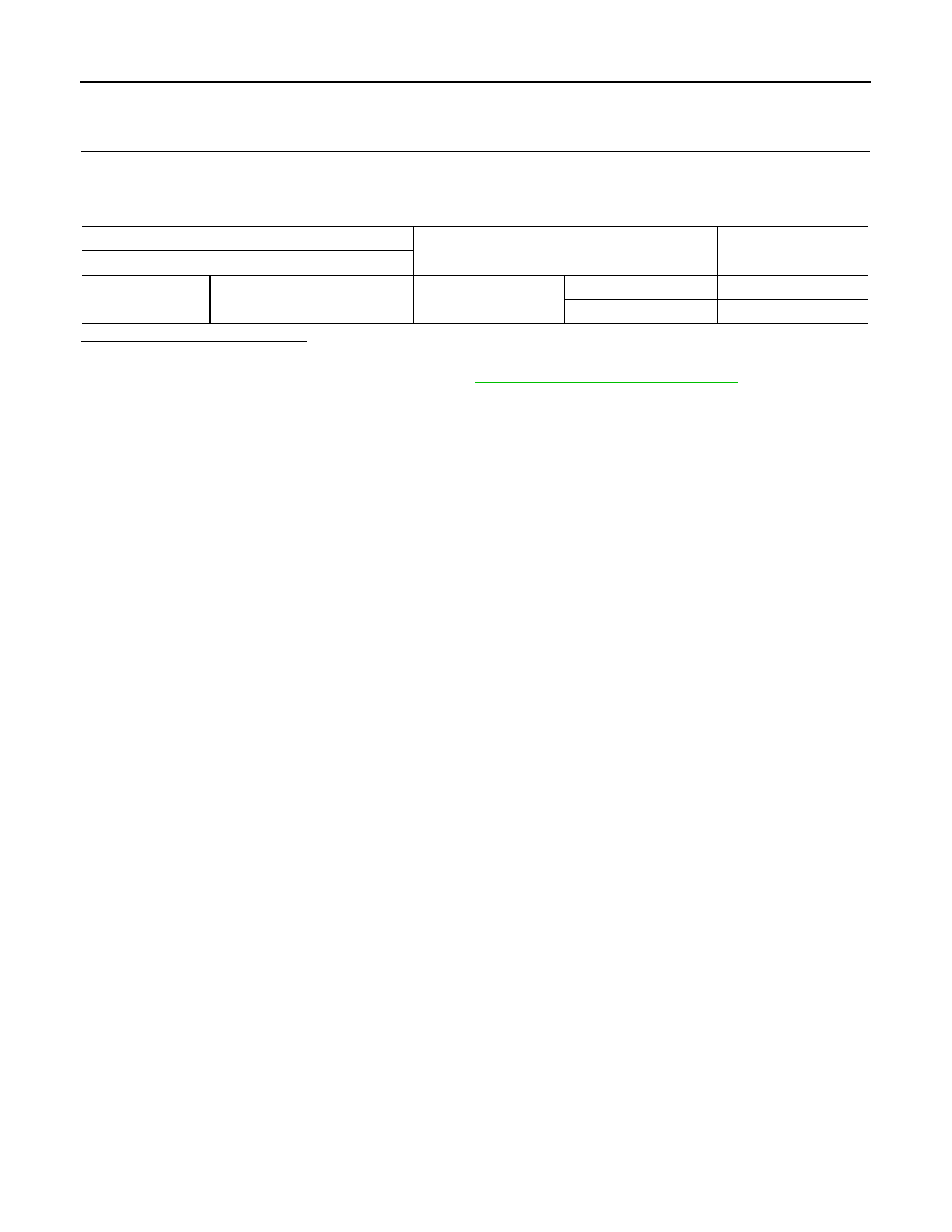
Component Inspection
INFOID:0000000009950482
1.
CHECK DOOR SWITCH
1.
Turn ignition switch OFF.
2.
Disconnect malfunctioning door switch connector.
3.
Check continuity between door switch terminals.
Is the inspection result normal?
YES
>> INSPECTION END
NO
>> Replace malfunction door switch. Refer to
DLK-225, "Removal and Installation"
Door switch
Condition
Continuity
Terminal
3
Ground part of door switch
Door switch
Pressed
Not existed
Released
Existed