Nissan Cube. Manual - part 133


  Index      Nissan     Nissan Cube (2014 year) - Service and Repair Manual


Search            


Content   ..  131  132  133  134   ..


Nissan Cube. Manual - part 133


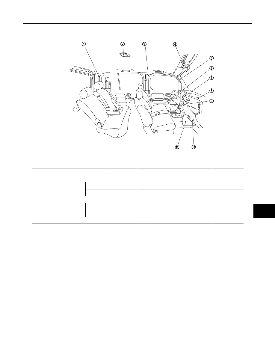
LOCATION OF PLASTIC PARTS

BRM-65

< SERVICE DATA AND SPECIFICATIONS (SDS) 

C

D

E

F

G

H

I

J

L

M

A

B

BRM

N

O

P

Component

Material

Component

Material

1

Rear pillar finisher

PP

6

Cluster lid A

PP

2

Room lamp

Lens

PC

7

Cluster lid C

PC + ABS

Housing

PP

8

Instrument panel

PP

3

Center pillar garnish

PP

9

Air conditioner control finisher

PC + ABS

4

Map  lamp

Lens

PC

10

Glove box

PP

Housing

PA

11

Instrument lower cover

PP

5

Front pillar garnish

PP

JSKIA1180ZZ

CCS-2

< SYSTEM DESCRIPTION >

[ASCD]

AUTOMATIC SPEED CONTROL DEVICE (ASCD)

SYSTEM DESCRIPTION

AUTOMATIC SPEED CONTROL DEVICE (ASCD)

Information

INFOID:0000000009949462

Automatic Speed Control Device (ASCD) system is controlled by ECM.
Regarding the information for ASCD system, refer to 

EC-65, "System Description"

.

CHG

CHG-1

ELECTRICAL & POWER CONTROL

C

D

E

F

G

H

I

J

K

L

B

SECTION 

CHG

A

O

P

N

CONTENTS

CHARGING SYSTEM

BASIC INSPECTION  ....................................

3

DIAGNOSIS AND REPAIR WORK FLOW  .........

3

Work Flow (With EXP-800 NI or GR8-1200 NI)  ........

3

Work Flow (Without EXP-800 NI or GR8-1200 NI) 

......

7

SYSTEM DESCRIPTION  .............................

10

CHARGING SYSTEM .........................................

10

System Diagram ......................................................

10

System Description  .................................................

10

Component Parts Location ......................................

10

Component Description ..........................................

11

POWER GENERATION VOLTAGE VARI-
ABLE CONTROL SYSTEM ................................

12

System Diagram ......................................................

12

System Description  .................................................

12

Component Parts Location ......................................

12

Component Description ...........................................

13

DTC/CIRCUIT DIAGNOSIS  .........................

14

B TERMINAL CIRCUIT  ......................................

14

Description ..............................................................

14

Diagnosis Procedure ...............................................

14

L TERMINAL CIRCUIT (OPEN)  .........................

15

Description ..............................................................

15

Diagnosis Procedure ...............................................

15

L TERMINAL CIRCUIT (SHORT) .......................

17

Description ..............................................................

17

Diagnosis Procedure ...............................................

17

S TERMINAL CIRCUIT  ......................................

18

Description ..............................................................

18

Diagnosis Procedure ...............................................

18

CHARGING SYSTEM .........................................

19

Wiring Diagram - CHARGING SYSTEM -  ...............

19

SYMPTOM DIAGNOSIS  ..............................

23

CHARGING SYSTEM  .......................................

23

Symptom Table  .......................................................

23

PRECAUTION ..............................................

24

PRECAUTIONS .................................................

24

Precaution for Supplemental Restraint System 
(SRS) "AIR BAG" and "SEAT BELT PRE-TEN-
SIONER" .................................................................

24

Precaution for Power Generation Voltage Variable 
Control System  ........................................................

24

Precautions for Removing of Battery Terminal ........

24

PREPARATION ...........................................

26

PREPARATION .................................................

26

Special Service Tools  ..............................................

26

Commercial Service Tools .......................................

26

PERIODIC MAINTENANCE  ........................

27

CHARGING SYSTEM PRELIMINARY IN-
SPECTION ........................................................

27

Inspection Procedure ...............................................

27

POWER GENERATION VOLTAGE VARI-
ABLE CONTROL SYSTEM OPERATION IN-
SPECTION ........................................................

28

Inspection Procedure ...............................................

28

REMOVAL AND INSTALLATION  ...............

30

ALTERNATOR ..................................................

30

Exploded View .........................................................

30

Removal and Installation  .........................................

31

Inspection ................................................................

31

SERVICE DATA AND SPECIFICATIONS 
(SDS) ............................................................

33

SERVICE DATA AND SPECIFICATIONS 
(SDS) .................................................................

33


Content   ..  131  132  133  134   ..