Nissan Cube. Manual - part 1038


  Index      Nissan     Nissan Cube (2014 year) - Service and Repair Manual


Search            


Content   ..  1036  1037  1038  1039   ..


Nissan Cube. Manual - part 1038


NOISE, VIBRATION AND HARSHNESS (NVH) TROUBLESHOOTING

WT-43

< SYMPTOM DIAGNOSIS >

C

D

F

G

H

I

J

K

L

M

A

B

WT

N

O

P

NOISE, VIBRATION AND HARSHNESS (NVH) TROUBLESHOOTING

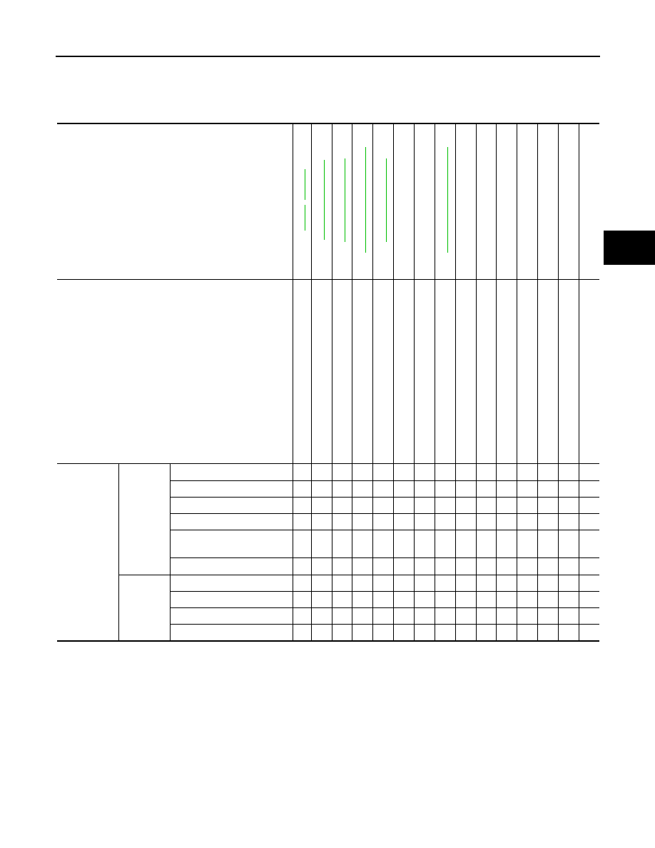
NVH Troubleshooting Chart

INFOID:0000000009949883

Use chart below to find the cause of the symptom. If necessary, repair or replace these parts.

×

: Applicable

Reference

FSU-9

FSU-1

1

WT

-46, "

In

sp

ecti

on

"

WT

-44, "

Adj

u

stment

"

WT

-54,

 "

T

ire Air Pressure

"

WT

-44, "

Adj

u

stment

"

WT

-54,

 "

T

ire Air Pressure

"

NVH in F

AX and FSU sections.

NVH 

in 

RAX and RSU sections.

Re

fer t

o

 T

IRES i

n

 t

h

is cha

rt.

Re

fe

r to

 ROAD WHEEL

 in

 th

is ch

art

.

NVH in F

AX section.

NVH in BR section.

NV

H

 in

 S

T

 s

e

cti

on

.

Possible cause and SUSPECTED PARTS

Imp

rop

er i

ns

ta

lla

ti

o

n,

 lo

os

en

es

s

Out

-of-ro

un

d

un

ba

lan

c

e

Incorrect t

ire 

pressure

Uneven tire 

wear

Def

o

rm

ati

o

n

 o

r da

ma

ge

No

n-u

n

if

ormi

ty

In

co

rrec

t t

ire 

si

ze

FRONT A

X

LE 

AND FRONT SUSP

ENSION

REAR A

X

LE 

AND REAR SUSP

ENSION

TI

RE

S

ROAD WHEE

LS

DRIVE SHAFT

BRAKE

STE

E

RING

Symptom

TIRES

Noise

×

×

×

×

×

×

×

×

×

×

×

×

×

Shake

×

×

×

×

×

×

×

×

×

×

×

×

×

Vibration

×

×

×

×

×

×

Shimmy

×

×

×

×

×

×

×

×

×

×

×

×

×

Judder

×

×

×

×

×

×

×

×

×

×

×

×

Poor quality ride or handling

×

×

×

×

×

×

×

×

×

×

ROAD 
WHEEL

Noise

×

×

×

×

×

×

×

×

×

×

Shake

×

×

×

×

×

×

×

×

×

×

Shimmy, Judder

×

×

×

×

×

×

×

×

×

Poor quality ride or handling

×

×

×

×

×

×

×

WT-44

< PERIODIC MAINTENANCE >

ROAD WHEEL

PERIODIC MAINTENANCE

ROAD WHEEL

Adjustment

INFOID:0000000009949884

BALANCING WHEELS (BONDING WEIGHT TYPE)

Preparation Before Adjustment

Using releasing agent, remove double-faced adhesive tape from the road wheel.

CAUTION:

• Be careful not to scratch the road wheel during removal.
• After removing double-faced adhesive tape, wipe clean traces of releasing agent from the road

wheel.

Wheel Balance Adjustment

• The details of the adjustment procedure are different for each model of wheel balancer. Therefore, refer to

each instruction manual.

• If a tire balance machine has adhesion balance weight mode settings and drive-in weight mode setting,

select and adjust a drive-in weight mode suitable for road wheels.

1.

Set road wheel on tire balance machine using the center hole as a guide. Start the tire balance machine.

2.

When inner and outer unbalance values are shown on the tire balance machine indicator, multiply outer
unbalance value by 5/3 to determine balance weight that should be used. Select the outer balance weight
with a value closest to the calculated value above and install to the designated outer position of, or at the
designated angle in relation to the road wheel.

CAUTION:

• Do not install the inner balance weight before installing the outer balance weight.
• Before installing the balance weight, be sure to clean the mating surface of the road wheel.

a.

Indicated unbalance value 

×

 5/3 = balance weight to be installed

Calculation example:
23 g (0.81 oz) 

×

 5/3 = 38.33 g (1.35 oz) 

 40 g (1.41 oz) bal-

ance weight (closer to calculated balance weight value)
NOTE:
Note that balance weight value must be closer to the calculated
balance weight value.
Example:
37.4 

 35 g (1.23 oz)

37.5 

 40 g (1.41 oz)

b.

Installed balance weight in the position.

SMA054D

ROAD WHEEL

WT-45

< PERIODIC MAINTENANCE >

C

D

F

G

H

I

J

K

L

M

A

B

WT

N

O

P

• When installing balance weight (1) to road wheels, set it into

the grooved area (A) on the inner wall of the road wheel as
shown in the figure so that the balance weight center (B) is
aligned with the tire balance machine indication position
(angle) (C).

CAUTION:

• Always use genuine NISSAN adhesion balance weights.
• Balance weights are non-reusable; always replace with

new ones.

• Do not install three or more sheets of balance weight.

c.

If calculated balance weight value exceeds 50 g (1.76 oz), install
two balance weight sheets in line with each other as shown in
the figure.

CAUTION:

Do not install one balance weight sheet on top of another.

3.

Start the tire balance machine again.

4.

Install drive-in balance weight on inner side of road wheel in the
tire balance machine indication position (angle).

CAUTION:

Do not install three or more balance weight.

5.

Start the tire balance machine. Check that inner and outer resid-
ual unbalance values is within the allowable unbalance value.

CAUTION:

If either residual unbalance value exceeds limit, repeat installation procedures.

TIRE ROTATION

• Follow the maintenance schedule for tire rotation service intervals.

Refer to 

MA-4, "Explanation of General Maintenance"

.

• When installing the wheel, tighten wheel nuts to the specified

torque. Refer to 

WT-46, "Exploded View"

.

CAUTION:

• Never include the T-type spare tire when rotating the tires.
• When installing wheels, tighten them diagonally by dividing

the work two to three times in order to prevent the wheels
from developing any distortion.

• Be careful not to tighten wheel nut at torque exceeding the

criteria for preventing strain of disc rotor.

• Use NISSAN genuine wheel nuts for aluminum wheels.

• Perform the ID registration, after tire rotation. Refer to 

WT-24, "Work Procedure"

.

JPEIC0040ZZ

Allowable unbalance value

Dynamic (At flange)

: Refer to 

WT-54, "Road Wheel"

.

Static (At flange)

: Refer to 

WT-54, "Road Wheel"

.

PEIA0033E

SMA829C

WT-46

< REMOVAL AND INSTALLATION >

ROAD WHEEL TIRE ASSEMBLY

REMOVAL AND INSTALLATION

ROAD WHEEL TIRE ASSEMBLY

Exploded View

INFOID:0000000009949885

Removal and Installation

INFOID:0000000009949886

REMOVAL

1.

Remove wheel nuts.

2.

Remove tire assembly.

INSTALLATION

Note the following, install in the reverse order of removal.
• When replacing or rotating wheels, perform the ID registration. Refer to 

WT-24, "Work Procedure"

.

Inspection

INFOID:0000000009949887

ALUMINUM WHEEL

1.

Check tires for wear and improper inflation.

2.

Check wheels for deformation, cracks and other damage. If deformed, remove wheel and check wheel
runout.

a.

Remove tire from aluminum wheel and mount on a tire balance machine.

b.

Set dial indicator as shown in the figure.

c.

Check runout, If the axial runout (A) or radial runout (B) exceeds
the limit, replace aluminum wheel.

STEEL WHEEL

1.

Check tires for wear and improper inflation.

1.

Tire assembly

Refer to 

GI-4, "Components"

 for symbols in the figure.

JSGIA0640GB

Limit

Axial runout (A)

: Refer to 

WT-54, "Road Wheel"

.

Radial runout (B)

: Refer to 

WT-54, "Road Wheel"

.

SEIA0737E


Content   ..  1036  1037  1038  1039   ..