Content .. 1002 1003 1004 1005 ..
Nissan Cube. Manual - part 1004
WCS
DIAGNOSIS SYSTEM (BCM) (WITH INTELLIGENT KEY SYSTEM)
WCS-19
< SYSTEM DESCRIPTION >
C
D
E
F
G
H
I
J
K
L
M
B
A
O
P
DATA MONITOR
NOTE:
The following table includes information (items) inapplicable to this vehicle. For information (items) applicable
to this vehicle, refer to CONSULT display items.
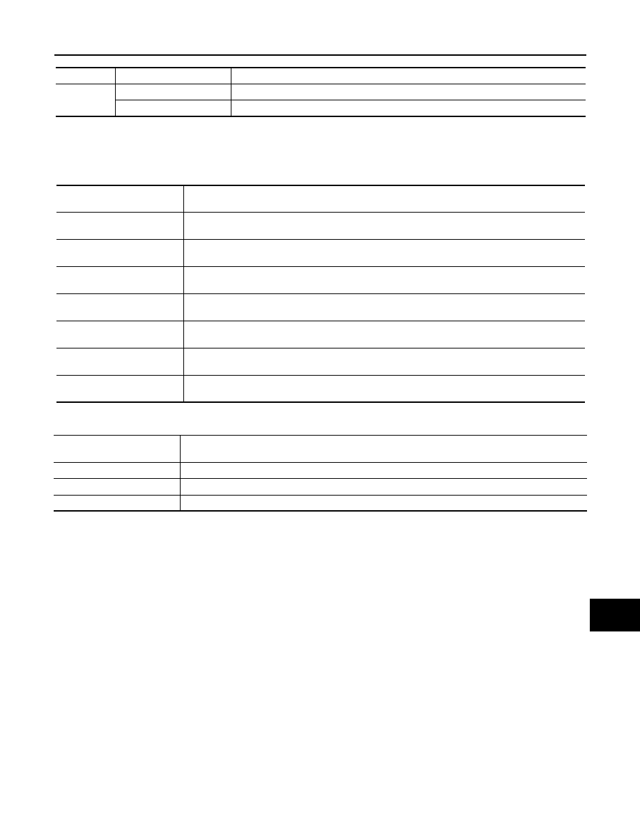
ACTIVE TEST
Test item
Diagnosis mode
Description
BUZZER
Data Monitor
Displays BCM input data in real time.
Active Test
Operation of electrical loads can be checked by sending driving signal to them.
Display item
[Unit]
Description
PUSH SW
[On/Off]
Status of push-button ignition switch judged by BCM.
UNLK SEN-DR
[On/Off]
Status of unlock sensor judged by BCM.
VEH SPEED 1
[km/h]
Value of vehicle speed signal received from combination meter with CAN communication line.
TAIL LAMP SW
[On/Off]
Status of lighting switch judged by BCM using the combination switch readout function.
FR FOG SW
[On/Off]
Status of front fog lamp switch judged by BCM using the combination switch readout function.
DOOR SW-DR
[On/Off]
Status of driver side door switch judged by BCM.
CDL LOCK SW
[On/Off]
Status of door lock unlock switch judged by BCM.
Display item
[Unit]
Description
SEAT BELT WARN TEST
The seat belt warning chime operation can be checked by operating the relevant function (On/Off).
ID REGIST WARNING
The ID regist warning chime operation can be checked by operating the relevant function (On/Off).
LIGHT WARN ALM
The light warning chime operation can be checked by operating the relevant function (On/Off).