Nissan Cube. Manual - part 1002


  Index      Nissan     Nissan Cube (2014 year) - Service and Repair Manual


Search            


Content   ..  1000  1001  1002  1003   ..


Nissan Cube. Manual - part 1002


WCS

WARNING CHIME SYSTEM

WCS-11

< SYSTEM DESCRIPTION >

C

D

E

F

G

H

I

J

K

L

M

B

A

O

P

Parking brake release warning chime judges the remaining parking brake according to the vehicle speed sig-
nal received from the ABS actuator and electric unit (control unit) via CAN communication and the parking
brake switch signal from parking brake switch to sound the warning buzzer. 

WARNING OPERATION CONDITIONS

If all of the following conditions are fulfilled.

WARNING CANCEL CONDITIONS

Warning is canceled if any of the following conditions are fulfilled.

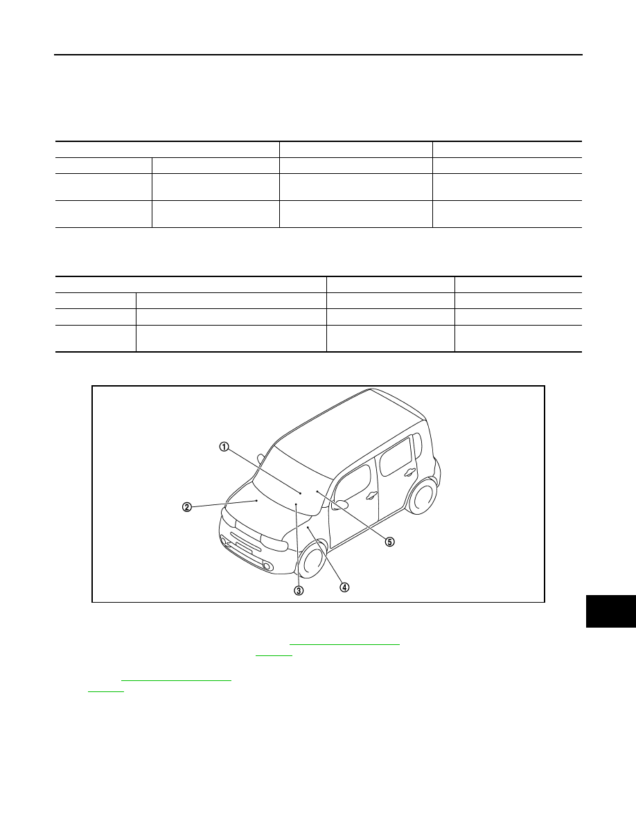
PARKING BRAKE RELEASE WARNING CHIME : Component Parts Location

INFOID:0000000009945507

Operation conditions

Signal name

Signal source

Ignition switch

ON

Ignition switch signal

Parking brake

During the operation (parking 
brake switch ON)

Parking brake switch signal

Parking brake switch

Vehicle speed

Approximately 7 km/h (4.3 
MPH) or more

Vehicle speed signal
(CAN communication)

ABS actuator and electric unit (con-
trol unit)

Operation conditions

Signal name

Signal source

Ignition switch

OFF

Ignition switch signal

Parking brake

Release condition (parking brake switch OFF)

Parking brake switch signal

Parking brake switch

Vehicle speed

Approximately 3 km/h (1.9 MPH) or more

Vehicle speed signal
(CAN communication)

ABS actuator and electric unit 
(control unit)

JPNIA1685ZZ

1.

Parking brake switch 

2.

ABS actuator and electric unit (con-
trol unit)
Refer to 

BRC-12, "Component Parts 

Location"

.

3.

Combination meter

4.

BCM
Refer to 

BCS-10, "Component Parts 

Location"

.

5.

Seat belt buckle switch (driver side)

WCS-12

< SYSTEM DESCRIPTION >

WARNING CHIME SYSTEM

PARKING BRAKE RELEASE WARNING CHIME : Component Description

INFOID:0000000009945508

KEY WARNING CHIME

KEY WARNING CHIME : System Diagram

INFOID:0000000009945509

KEY WARNING CHIME : System Description

INFOID:0000000009945510

DESCRIPTION

With ignition switch in the OFF or ACC position, when the driver side door is open (driver side door switch ON)
and the key inserted into the ignition key cylinder (key switch ON), the warning chime will sound.

WARNING OPERATION CONDITIONS

The BCM transmits the buzzer output signal to combination meter with CAN communication line when all of
the following operation conditions are met. When combination meter receives buzzer output signal, it sounds
the buzzer.

WARNING CANCEL CONDITIONS

Warning is canceled if any of the following conditions is fulfilled.

Unit

Description

Combination meter

Judges the remaining parking brake according to the vehicle speed signal received from the ABS 
actuator and electric unit (control unit) via CAN communication and the parking brake switch signal 
from parking brake switch and sounds the warning buzzer. 

ABS actuator and electric unit 
(control unit)

Transmits the vehicle speed signal to the combination meter via CAN communication. 

Parking brake switch

Transmits the parking brake switch signal to the combination meter. 

JPNIA1691GB

Operation conditions

Signal name

Signal source

Ignition switch

OFF or ACC position

Ignition switch signal

Key switch

ON (state that inserted key in key 
cylinder)

Key switch signal

Key switch

Driver side door

Open (driver side door switch ON)

Driver side door switch signal

Driver side door switch

Operation conditions

Signal name

Signal source

Ignition switch

ON

Ignition switch signal

Key switch

OFF (state that removed key from 
key cylinder)

Key switch signal

Key switch

Driver side door

Close (driver side door switch OFF)

Driver side door switch signal

Driver side door switch

WCS

WARNING CHIME SYSTEM

WCS-13

< SYSTEM DESCRIPTION >

C

D

E

F

G

H

I

J

K

L

M

B

A

O

P

KEY WARNING CHIME : Component Parts Location

INFOID:0000000009945511

KEY WARNING CHIME : Component Description

INFOID:0000000009945512

JPNIA1685ZZ

1.

Parking brake switch 

2.

ABS actuator and electric unit (con-
trol unit)
Refer to 

BRC-12, "Component Parts 

Location"

.

3.

Combination meter

4.

BCM
Refer to 

BCS-10, "Component Parts 

Location"

.

5.

Seat belt buckle switch (driver side)

Unit

Description

Combination meter

Receives a buzzer output signal from the BCM and sounds the buzzer.

BCM

Judges the key warning conditions from the signals provided by various switches and transmits a 
buzzer output signal to the combination meter via CAN communication if necessary. 

Key switch

Transmits the key switch signal to BCM.

Driver side door switch

Transmits the driver side door switch signal to BCM.

WCS-14

< SYSTEM DESCRIPTION >

DIAGNOSIS SYSTEM (METER)

DIAGNOSIS SYSTEM (METER)

CONSULT Function (METER/M&A)

INFOID:0000000010244837

CONSULT APPLICATION ITEMS

CONSULT can perform the following diagnosis modes via CAN communication and the combination meter.

SELF DIAG RESULT

Refer to 

MWI-62, "DTC Index"

.

DATA MONITOR

NOTE:
The following table includes information (items) inapplicable to this vehicle. For information (items) applicable
to this vehicle, refer to CONSULT display items.

Display Item List

X: Applicable

System

Diagnosis mode

Description

METER/M&A

Self Diagnostic Result

The combination meter checks the conditions and displays memorized errors.

Data Monitor

Displays the combination meter input/output data in real time.

Warning History

Lighting history of the warning lamp and indicator lamp can be checked.

Display item [Unit]

MAIN

SIGNALS

Description

SPEED METER
[km/h]

X

Value of vehicle speed signal received from ABS actuator and electric unit (control 
unit) via CAN communication.
NOTE:
655.35 is displayed when the malfunction signal is received.

SPEED OUTPUT
[km/h]

X

Vehicle speed signal value transmitted to other units via CAN communication.
NOTE:
655.35 is displayed when the malfunction signal is received.

ODO OUTPUT
[km/h or mph]

Odometer signal value transmitted to other units via CAN communication.

TACHO METER
[rpm]

X

Value of the engine speed signal received from ECM via CAN communication.
NOTE:
8191.875 is displayed when the malfunction signal is received.

FUEL METER
[L]

X

Fuel level indicated on combination meter.

W TEMP METER
[

°

C] 

X

Value of engine coolant temperature signal is received from ECM via CAN com-
munication. 
NOTE:
215 is displayed when the malfunction signal is input.

FUEL CAP W/L
[On/Off]

Status of fuel filler cap warning display detected from fuel filler cap warning display 
signal received from ECM via CAN communication.

ABS W/L
[On/Off]

Status of ABS warning lamp detected from ABS warning lamp signal is received 
from ABS actuator and electric unit (control unit) via CAN communication.

VDC/TCS IND
[On/Off]

Status of VDC OFF indicator lamp detected from VDC OFF indicator lamp signal 
is received from ABS actuator and electric unit (control unit) via CAN communica-
tion.

SLIP IND
[On/Off]

Status of VDC warning lamp detected from VDC warning lamp signal received 
from ABS actuator and electric unit (control unit) via CAN communication.

BRAKE W/L
[On/Off]

Status of brake warning lamp detected from brake warning lamp signal is received 
from ABS actuator and electric unit (control unit) via CAN communication.
NOTE:
Displays “Off” if the brake warning lamp is illuminated when the valve check starts, 
the parking brake switch is turned ON or the brake fluid level switch is turned ON.

DOOR W/L
[On/Off]

Status of door warning detected from door switch signal received from BCM via 
CAN communication.


Content   ..  1000  1001  1002  1003   ..