Nissan Cube. Manual - part 83
BRAKE MASTER CYLINDER
BR-25
< REMOVAL AND INSTALLATION >
C
D
E
G
H
I
J
K
L
M
A
B
BR
N
O
P
BRAKE MASTER CYLINDER
Exploded View
INFOID:0000000009949222
Removal and Installation
INFOID:0000000009949223
REMOVAL
CAUTION:
• Never spill or splash brake fluid on painted surfaces. Brake fluid may seriously damage paint. Wipe it
off immediately and wash with water if it gets on a painted surface.
• Depress the brake pedal several times to release the vacuum pressure from the brake booster. Then
remove the master cylinder assembly.
1.
Remove cowl top cover and extension cowl top. Refer to
2.
Remove air duct and air cleaner case. Refer to
3.
Drain brake fluid. Refer to
4.
Disconnect the brake fluid level switch harness connector.
5.
Remove the brake tube from between ABS actuator and electric unit (control unit) and master cylinder
assembly with a flare nut wrench.
CAUTION:
Never scratch the flare nut and the brake tube.
6.
Remove the master cylinder assembly.
CAUTION:
• Never deform or bend the brake tubes.
• Never depress the brake pedal after the master cylinder assembly is removed.
• The piston of the master cylinder assembly is exposed. Never damage it when removing the
master cylinder.
• The piston may drop off when pulled out strongly. Never hold the piston. Hold the cylinder body
when handling the master cylinder assembly.
INSTALLATION
CAUTION:
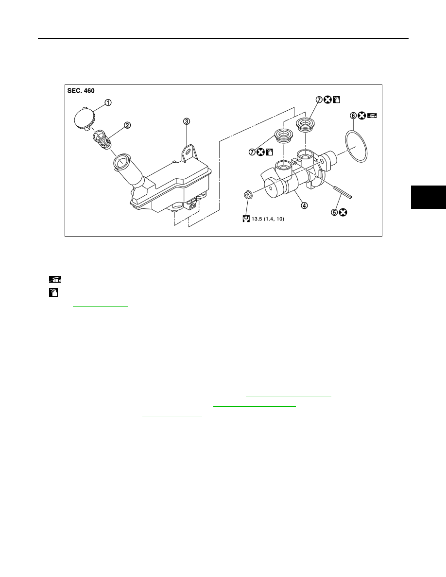
1.
Reservoir cap
2.
Oil strainer
3.
Reservoir tank
4.
Cylinder body
5.
Pin
6.
O-ring
7.
Grommet
: Apply PBC (Poly Butyl Cuprysil) grease or silicone-based grease.
: Apply brake fluid.
Refer to
for symbols not described on the above.
JPFIA0544GB