Nissan Cube. Manual - part 78


  Index      Nissan     Nissan Cube (2014 year) - Service and Repair Manual


Search            


Content   ..  76  77  78  79   ..


Nissan Cube. Manual - part 78


PRECAUTIONS

BR-5

< PRECAUTION >

C

D

E

G

H

I

J

K

L

M

A

B

BR

N

O

P

• After pressing the brake pedal more deeply or harder than normal driving, such as air bleeding, check each

item of brake pedal. Adjust brake pedal if it is outside the standard value. 

• Always clean with new brake fluid when cleaning the master cylinder, brake caliper and other components.
• Never use mineral oils such as gasoline or light oil to clean. They may damage rubber parts and cause

improper operation.

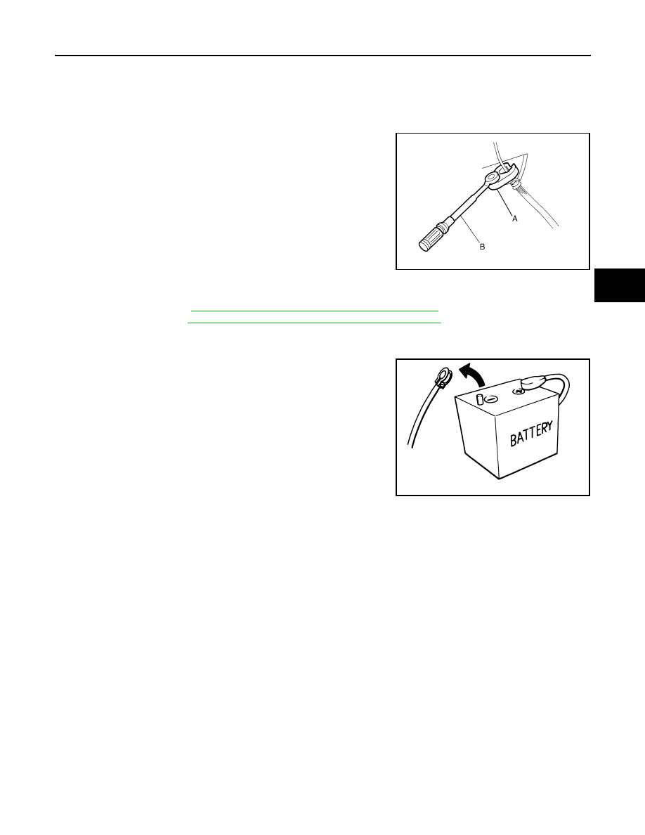
• Always loosen the brake tube flare nut with a flare nut wrench.
• Tighten the brake tube flare nut to the specified torque with a crow-

foot (A) and torque wrench (B).

• Always confirm the specified tightening torque when installing the

brake pipes.

• Brake system is an important safety part. If a brake fluid leak is

detected, always disassemble the affected part. If a malfunction is
detected, replace part with a new one.

• Turn the ignition switch OFF and disconnect the ABS actuator and

electric unit (control unit) connector or the battery negative terminal
before performing the work.

• Check that no brake fluid leakage is present after replacing the

parts.

• Burnish the brake contact surfaces after refinishing or replacing rotors, after replacing pads, or if a soft pedal

occurs at very low mileage. 

- Front brake pad: Refer to 

BR-14, "BRAKE PAD : Inspection and Adjustment"

.

- Front disc rotor: Refer to 

BR-14, "DISC ROTOR : Inspection and Adjustment"

.

Precautions for Removing of Battery Terminal

INFOID:0000000010078174

•  When removing the 12V battery terminal, turn OFF the ignition

switch and wait at least 30 seconds.
NOTE:
ECU may be active for several tens of seconds after the ignition
switch is turned OFF. If the battery terminal is removed before ECU
stops, then a DTC detection error or ECU data corruption may
occur.

•  For vehicles with the 2-batteries, be sure to connect the main bat-

tery and the sub battery before turning ON the ignition switch.
NOTE:
If the ignition switch is turned ON with any one of the terminals of
main battery and sub battery disconnected, then DTC may be
detected.

•  After installing the 12V battery, always check "Self Diagnosis Result" of all ECUs and erase DTC.

NOTE:
The removal of 12V battery may cause a DTC detection error.

JPFIA0001ZZ

SEF289H

BR-6

< PREPARATION >

PREPARATION

PREPARATION

PREPARATION

Commercial Service Tool

INFOID:0000000009949199

Tool name

Description

Power tool

Loosening bolts and nuts

Handy vacuum pump

• Air  tight
• Inspection of check valve

Brake caliper wrench

Return the piston

PBIC0190E

ZZC1313D

NNFIA0040ZZ

BRAKE PEDAL

BR-7

< PERIODIC MAINTENANCE >

C

D

E

G

H

I

J

K

L

M

A

B

BR

N

O

P

PERIODIC MAINTENANCE

BRAKE PEDAL

Inspection and Adjustment

INFOID:0000000009949200

INSPECTION

Brake Pedal Height

Check the height (H

1

) between the dash lower panel (1) and the

brake pedal upper surface.

CAUTION:

Remove the floor trim.

Stop Lamp Switch

Check the clearance (C) among the brake pedal lever (1) and the
stop lamp switch (2) threaded end.

CAUTION:

The stop lamp must turn off when the brake pedal is released.
NOTE:
Pull the brake pedal pad to make the clearance between the stop
lamp switch threaded end and the brake peal lever.

ASCD Brake Switch (With ASCD)

Check the clearance (C) among the brake pedal bracket (1) and the
ASCD brake switch (2) threaded end.

NOTE:
Pull the brake pedal pad to make the clearance between the ASCD
brake switch threaded end and the brake peal bracket.

Brake Pedal Play

Press the brake pedal. Check the brake pedal play (A) (stroke until
fluid pressure occurs).

Depressed Brake Pedal Height

H

1

: Refer to 

BR-43, "Brake Pedal"

.

JPFIA0065ZZ

C

: Refer to 

BR-43, "Brake Pedal"

.

PFIA0813J

C

: Refer to 

BR-43, "Brake Pedal"

.

JPFIA0674ZZ

A

:  Refer  to 

BR-43, "Brake Pedal"

.

JPFIA0277ZZ

BR-8

< PERIODIC MAINTENANCE >

BRAKE PEDAL

Check the height between the dash lower panel (1) and the brake
pedal upper surface (H

2

) when depressing the brake pedal at 490 N

(50 kg, 110 lb) while turning engine ON.

CAUTION:

Remove the floor trim.

ADJUSTMENT

Brake Pedal Height

1.

Remove instrument lower panel LH. Refer to 

IP-13, "Exploded View"

.

2.

Disconnect the harness connector from ASCD brake switch and stop lamp switch.

3.

Loosen the ASCD brake switch and stop lamp switch 45

°

 counterclockwise.

4.

Adjust the brake pedal height with the following procedure.

a.

Loosen the input rod lock nut (1).

CAUTION:

The threaded end of the input rod (2) must project to the
inner side (L) of the clevis (3).

b.

Rotate the input rod, adjust the brake pedal to the specified
height (H

1

).

c.

Tighten the lock nut. Refer to 

BR-28, "Exploded View"

.

5.

Check the brake pedal play.

Brake Pedal Play

NOTE:
The clearance between the stop lamp switch threaded end and the brake pedal lever and the clearance
between the ASCD brake switch threaded end and the brake pedal bracket (with ASCD) are adjusted by
adjusting play of the brake pedal.
1.

Remove instrument lower panel LH. Refer to 

IP-13, "Exploded View"

.

2.

Disconnect the harness connector from ASCD brake switch (with ASCD) and stop lamp switch.

3.

Loosen the ASCD brake switch (with ASCD) and stop lamp switch 45

°

 counterclockwise.

H

2

: Refer to 

BR-43, "Brake Pedal"

.

JPFIA0068ZZ

JPFIA0003ZZ

H

1

: Refer to 

BR-43, "Brake Pedal"

.

JPFIA0279ZZ


Content   ..  76  77  78  79   ..