Nissan Cube. Manual - part 75
BCS
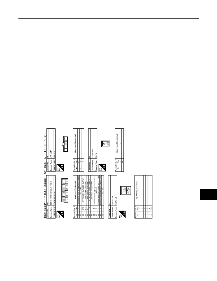
BCM (BODY CONTROL MODULE)
BCS-149
< ECU DIAGNOSIS INFORMATION >
[WITHOUT INTELLIGENT KEY SYSTEM]
C
D
E
F
G
H
I
J
K
L
B
A
O
P
N
Fail-safe
INFOID:0000000009949797
FAIL-SAFE CONTROL BY DTC
BCM performs fail-safe control when any DTC are detected.
JRMWE7831GB