Nissan Cube. Manual - part 6
AV
POWER SUPPLY AND GROUND CIRCUIT
AV-17
< DTC/CIRCUIT DIAGNOSIS >
[AUDIO WITHOUT NAVIGATION]
C
D
E
F
G
H
I
J
K
L
M
B
A
O
P
DTC/CIRCUIT DIAGNOSIS
POWER SUPPLY AND GROUND CIRCUIT
AUDIO UNIT
AUDIO UNIT : Diagnosis Procedure
INFOID:0000000009949543
1.
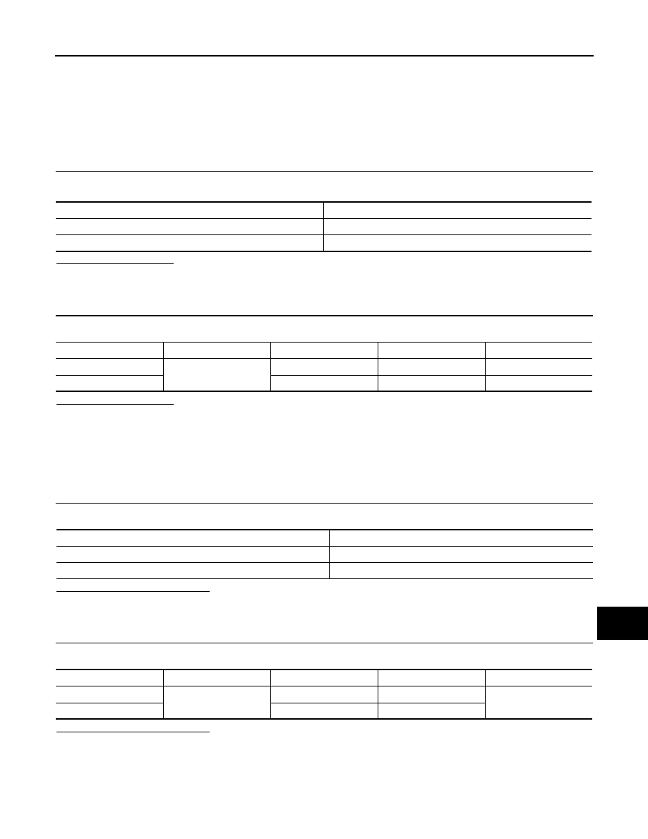
CHECK FUSE
Check that the following fuses of the audio unit are not blown.
Is inspection result OK?
YES
>> GO TO 2.
NO
>> If fuse is blown, be sure to eliminate cause of malfunction before installing new fuse.
2.
CHECK AUDIO UNIT POWER SUPPLY CIRCUIT
Check voltage between the audio unit and ground.
Is inspection result OK?
YES
>> INSPECTION END
NO
>> Check harness between audio unit and fuse.
iPod ADAPTER
iPod ADAPTER : Diagnosis Procedure
INFOID:0000000009949544
1.
CHECK FUSE
Check for blown fuses.
Is the inspection result normal?
YES
>> GO TO 2.
NO
>> Be sure to eliminate the cause of malfunction before installing new fuse.
2.
CHECK POWER SUPPLY CIRCUIT
Check voltage between iPod adapter harness connector and ground.
Is the inspection result normal?
YES
>> INSPECTION END
NO
>> Check harness between iPod adapter and fuse.
TEL ADAPTER UNIT
Power source
Fuse No.
Battery
34
Ignition switch ACC or ON
20
Signal name
Connector No.
Terminal No.
Ignition switch position
Voltage
Battery power supply
M46
19
OFF
Battery voltage
ACC power supply
7
ACC
Battery voltage
Power source
Fuse No.
Battery
34
Ignition switch ACC or ON
20
Signal name
Connector No.
Terminal No.
Ignition switch position
Voltage
Battery power supply
M99
5
OFF
Battery voltage
ACC power supply
3
ACC