Nissan Versa Note. Manual - part 868


  Index      Nissan     Nissan Versa Note (2014 year) - Service and Repair Manual


Search            


Content   ..  866  867  868  869   ..


Nissan Versa Note. Manual - part 868


WHEEL

WT-41

< PERIODIC MAINTENANCE >

C

D

F

G

H

I

J

K

L

M

A

B

WT

N

O

P

PERIODIC MAINTENANCE

WHEEL

Inspection

INFOID:0000000009446796

1. Check tires for wear and improper inflation.
2. Check wheels for deformation, cracks and other damage. If deformed, remove wheel and check wheel

runout.

a. Remove tire from wheel and mount wheel on a balancer machine.
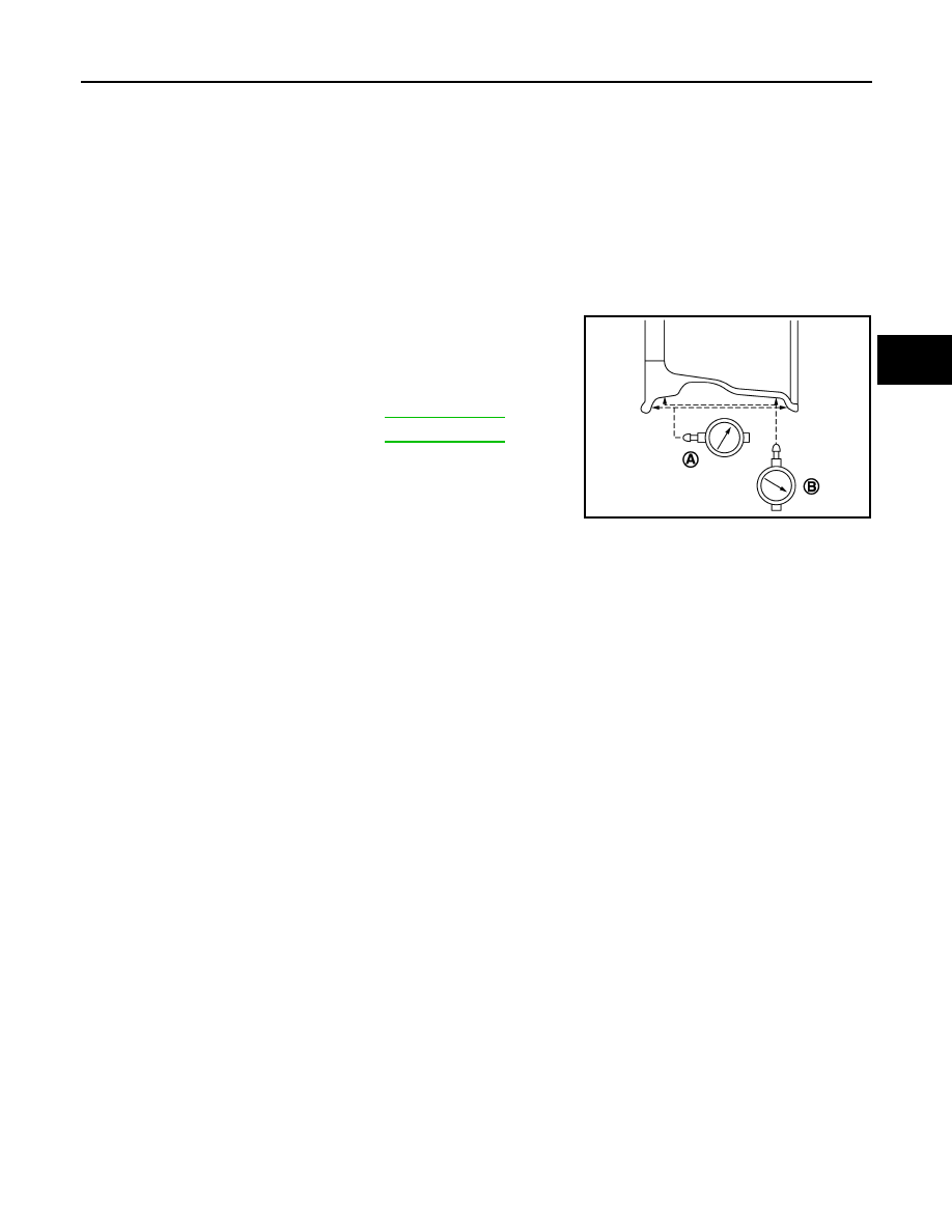
b. Set dial indicator as shown.
c. Check runout, if runout value exceeds the limit, replace wheel.

Limit
Axial Runout (A)

Refer to 

WT-50, "Wheel"

.

Radial Runout (B)

Refer to 

WT-50, "Wheel"

.

SEIA0737E

WT-42

< PERIODIC MAINTENANCE >

WHEEL AND TIRE

WHEEL AND TIRE

Adjustment

INFOID:0000000009446795

BALANCING WHEELS (ADHESIVE WEIGHT TYPE)

Preparation Before Adjustment

Remove inner and outer balance weights from the wheel and tire. Using releasing agent, remove double-faced

adhesive tape from the wheel and tire.

CAUTION:

• Be careful not to scratch the wheel and tire during removal.

• After removing double-faced adhesive tape, wipe clean all traces of releasing agent from the wheel

and tire.

Wheel Balance Adjustment

CAUTION:

• DO NOT use center hole cone-type clamping machines to hold the wheel during tire removal/installa-

tion or balancing or damage to the wheel paint, cladding or chrome may result. Use only rim-type or

universal lug-type clamping machines to hold the wheel during servicing.

• If a balancer machine has an adhesive weight mode setting, select the adhesive weight mode setting and

skip Step 2 below. If a balancer machine only has the clip-on (rim flange) weight mode setting, follow Step 2

to calculate the correct size adhesive weight.

1. Set wheel and tire on balancer machine using the center hole as a guide. Start the balancer machine.
2. For balancer machines that only have a clip-on (rim flange) weight mode setting, follow this step to calcu-

late the correct size adhesive weight to use. When inner and outer imbalance values are shown on the

balancer machine indicator, multiply outer imbalance value by 5/3 (1.67) to determine balance weight that

should be used. Select the outer balance weight with a value closest to the calculated value above and

install in to the designated outer position of or at the designated angle in relation to the wheel and tire.

a. Indicated imbalance value 

× 5/3 (1.67) = balance weight to be

installed

Calculation example:

23 g (0.81 oz) 

× 5/3 (1.67) = 38.33 g (1.35 oz) ⇒ 40 g (1.41 oz)

balance weight (closer to calculated balance weight value)

NOTE:

Note that balance weight value must be closer to the calculated

balance weight value.

Example:

37.4 

⇒ 35 g (1.23 oz)

37.5 

⇒ 40 g (1.41 oz)

SMA054D

WHEEL AND TIRE

WT-43

< PERIODIC MAINTENANCE >

C

D

F

G

H

I

J

K

L

M

A

B

WT

N

O

P

3. Install balance weight in the position shown.

CAUTION:

• Do not install the inner balance weight before installing

the outer balance weight.

• Before installing the balance weight, be sure to clean the

mating surface of the wheel and tire.

• When installing balance weight (1) to wheel and tire, set it into

the grooved area (A) on the inner wall of the wheel and tire as

shown so that the balance weight center (B) is aligned with the

balancer machine indication position (angle) (C).

CAUTION:

• Always use Genuine NISSAN adhesive balance weights.

• Balance weights are non-reusable; always replace with

new ones.

• Do not install more than three sheets of balance

weights.

4. If calculated balance weight value exceeds 50 g (1.76 oz), install

two balance weight sheets in line with each other as shown.

CAUTION:

Do not install one balance weight sheet on top of another.

5. Start balancer machine again.
6. Install balance weight on inner side of wheel and tire in the bal-

ancer machine indication position (angle).

CAUTION:

Do not install more than two balance weights.

7. Start balancer machine. Make sure that inner and outer residual

imbalance values are 5 g (0.17 oz) each or below.

8. If either residual imbalance value exceeds 5 g (0.17 oz), repeat installation procedures.

TIRE ROTATION

• Follow the maintenance schedule for tire rotation service intervals.

Refer to 

MA-7, "Introduction of Periodic Maintenance"

.

• Rotate the wheel and tires front to back in the pattern as shown.

• When installing the wheel, tighten wheel nuts to the specified

torque.

WARNING:

• After rotating the tires, check and adjust the tire pressure.

• Retighten the wheel nuts when the vehicle has been driven

for 1,000 km (600 mi) (also in case of a flat tire, etc.).

• Do not include the spare tire when rotating the tires.

CAUTION:

• When installing wheels, tighten them diagonally by dividing the work two to three times in order to

prevent the wheels from developing any distortion.

• Be careful not to tighten the wheel nuts to a torque exceeding specification to prevent strain on the

disc rotor.

• Use Genuine NISSAN wheel nuts.

JPEIC0040ZZ

Wheel balance

Dynamic (At flange)

Static (At flange)

Maximum allowable im-
balance

Refer to 

WT-50, "Wheel"

.

PEIA0033E

SMA829C

WT-44

< PERIODIC MAINTENANCE >

WHEEL AND TIRE

• Perform the ID registration after tire rotation. Refer to 

WT-22, "Work Procedure"

.

Wheel nut tightening 
torque

WT-45, "Exploded View"


Content   ..  866  867  868  869   ..