Nissan Versa Note. Manual - part 849
WCS-10
< SYSTEM DESCRIPTION >
SYSTEM
1. BCM requires warning chime output to combination meter when it judges seat belt warning chime is nec-
essary from signals below.
2. Combination meter sounds integrated buzzer, following the warning chime output requirement (below sig-
nal) from BCM.
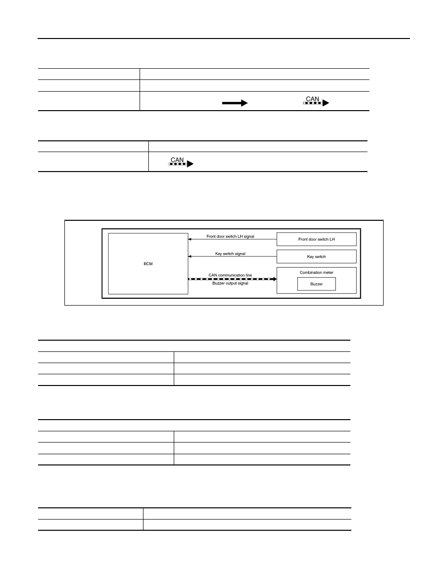
KEY WARNING CHIME
KEY WARNING CHIME : Key Warning Chime
INFOID:0000000009667997
SYSTEM DIAGRAM
WARNING CHIME OPERATION CONDITIONS
If all of the following conditions are fulfilled.
WARNING CHIME CANCEL CONDITIONS
Warning is canceled if any of the following conditions is fulfilled.
SIGNAL PATH
1. BCM detects key inserted into the ignition switch, and sends key warning signal to combination meter with
CAN communication line.
Signal name
Signal source
Ignition switch signal
—
Seat belt buckle switch signal (LH) Seat belt buckle switch (LH)
Combination meter
BCM
Signal name
Signal source
Buzzer output signal
BCM
Combination meter
AWNIA3130GB
Operation conditions
Ignition switch
OFF or ACC position
Key switch
ON (key is in key cylinder)
Driver side door
Open [front door switch LH ON]
Operation conditions
Ignition switch
ON
Key switch
ON (key is removed from key cylinder)
Driver side door
Close [front door switch LH OFF]
Signal name
Signal source
Ignition switch signal
—