Nissan Versa Note. Manual - part 830
TM-200
< DTC/CIRCUIT DIAGNOSIS >
[CVT: RE0F11A]
P1586 G SENSOR
4. Select “G SEN SLOPE”.
5. Swing the vehicle and check if value varies between
−40.45% and 40.45%.
Is the inspection result normal?
YES
>> GO TO 2.
NO
>> GO TO 3.
2.
G SENSOR CALIBRATION (PART 1)
With CONSULT
1. Select “Self Diagnostic Results” in “TRANSMISSION”.
2. Touch “Erase”.
>> Perform "G SENSOR CALIBRATION". Refer to
3.
CHECK SENSOR POWER SUPPLY
1. Turn ignition switch OFF.
2. Disconnect G sensor connector.
3. Turn ignition switch ON.
4. Check voltage between G sensor harness connector terminal and ground.
Is the inspection result normal?
YES
>> GO TO 4.
NO
>> GO TO 8.
4.
CHECK CIRCUIT BETWEEN TCM AND G SENSOR (PART 1)
1. Turn ignition switch OFF.
2. Disconnect TCM connector.
3. Check continuity between TCM harness connector terminals and G sensor harness connector terminals.
Is the inspection result normal?
YES
>> GO TO 5.
NO
>> Repair or replace malfunctioning parts.
5.
CHECK CIRCUIT BETWEEN TCM AND G SENSOR (PART 2)
Check continuity between TCM harness connector terminals and ground.
Is the inspection result normal?
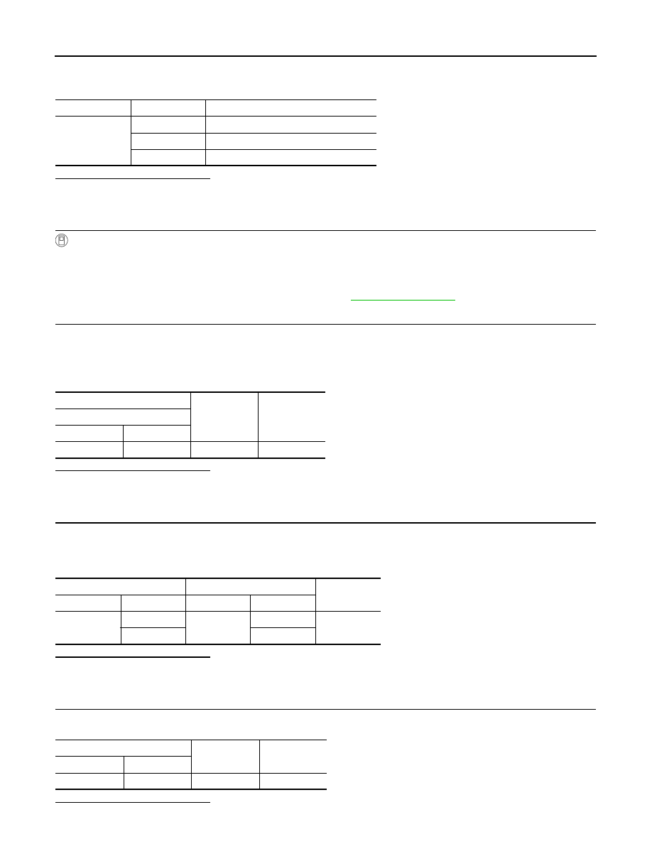
Monitor item
Condition
Standard
G SEN SLOPE
Flat road
0%
Uphill
Positive value (Maximum 40.45%)
Downhill
Negative value (Minimum
−40.45%)
+
−
Voltage
(Approx.)
G sensor
Connector
Terminal
M83
3
Ground
5.0 V
TCM
G sensor
Continuity
Connector
Terminal
Connector
Terminal
F44
11
M83
2
Existed
14
1
TCM
—
Continuity
Connector
Terminal
F44
14
Ground
Not existed