Nissan Versa Note. Manual - part 820
TM-160
< DTC/CIRCUIT DIAGNOSIS >
[CVT: RE0F11A]
P0715 INPUT SPEED SENSOR A
YES
>> GO TO 2.
NO
>> GO TO 6.
2.
CHECK PRIMARY SPEED SENSOR GROUND CIRCUIT
Check continuity between primary speed sensor harness connector terminal and ground.
Is the inspection result normal?
YES
>> GO TO 3.
NO
>> Repair or replace malfunctioning parts.
3.
CHECK CIRCUIT BETWEEN PRIMARY SPEED SENSOR AND TCM (PART 1)
1. Turn ignition switch OFF.
2. Disconnect TCM connector.
3. Check continuity between primary speed sensor harness connector terminal and TCM harness connector
terminal.
Is the inspection result normal?
YES
>> GO TO 4.
NO
>> Repair or replace malfunctioning parts.
4.
CHECK CIRCUIT BETWEEN PRIMARY SPEED SENSOR AND TCM (PART 2)
Check continuity between primary speed sensor harness connector terminal and ground.
Is the inspection result normal?
YES
>> GO TO 5.
NO
>> Repair or replace malfunctioning parts.
5.
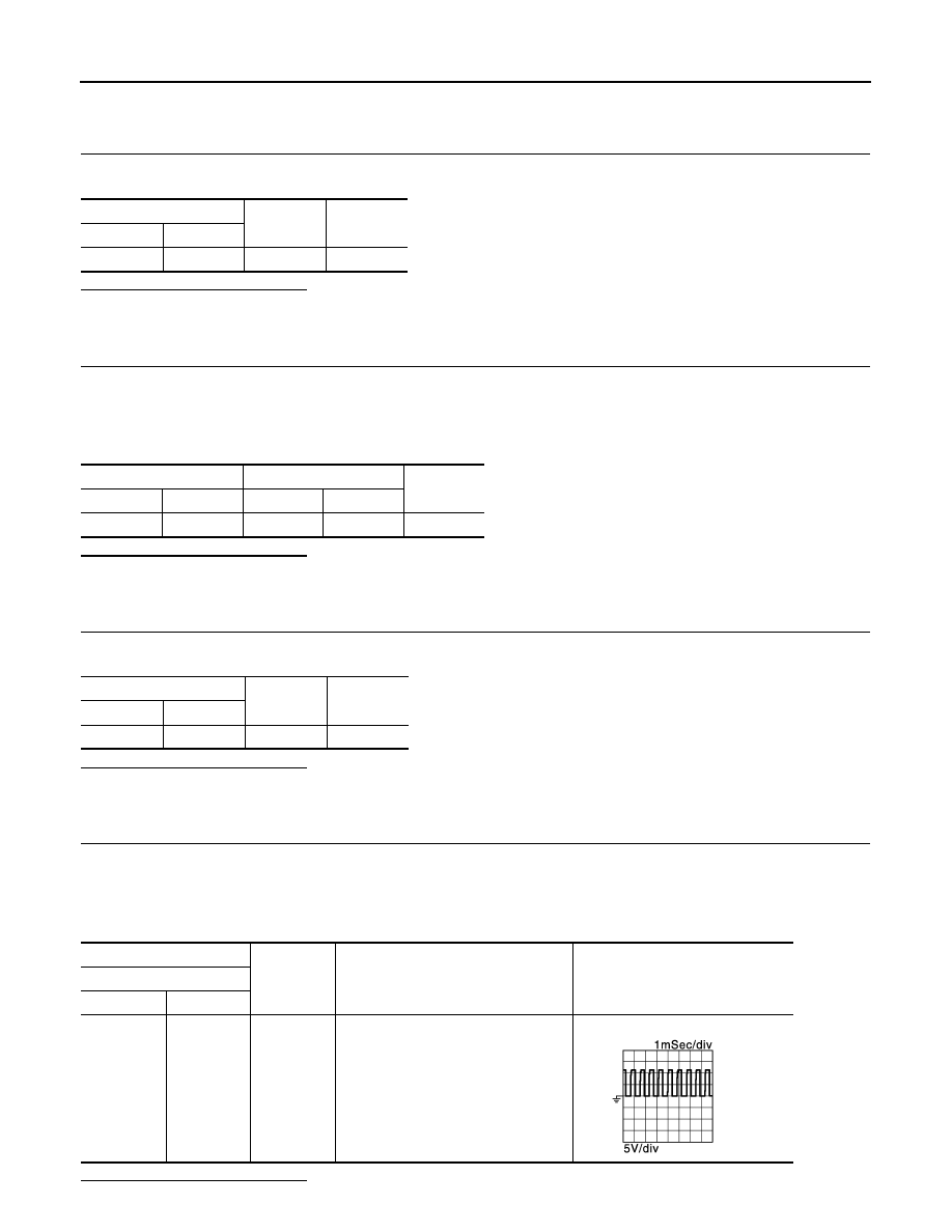
CHECK TCM INPUT SIGNALS
1. Connect all of disconnected connectors.
2. Lift the vehicle.
3. Start the engine.
4. Check frequency of primary speed sensor.
Is the inspection result normal?
Primary speed sensor
—
Continuity
Connector
Terminal
F50
1
Ground
Existed
Primary speed sensor
TCM
Continuity
Connector
Terminal
Connector
Terminal
F50
2
F44
35
Existed
Primary speed sensor
—
Continuity
Connector
Terminal
F50
2
Ground
Not existed
+
−
Condition
Frequency
(Approx.)
TCM
Connector
Terminal
F44
35
Ground
• Selector lever: “L” position
• Vehicle speed: 20 km/h (12 MPH)
1,100 Hz
JSDIA1906GB