Nissan Versa Note. Manual - part 764


  Index      Nissan     Nissan Versa Note (2014 year) - Service and Repair Manual


Search            


Content   ..  762  763  764  765   ..


Nissan Versa Note. Manual - part 764


COMPONENT PARTS

STC-5

< SYSTEM DESCRIPTION >

C

D

E

F

H

I

J

K

L

M

A

B

STC

N

O

P

EPS Control Unit

INFOID:0000000009667171

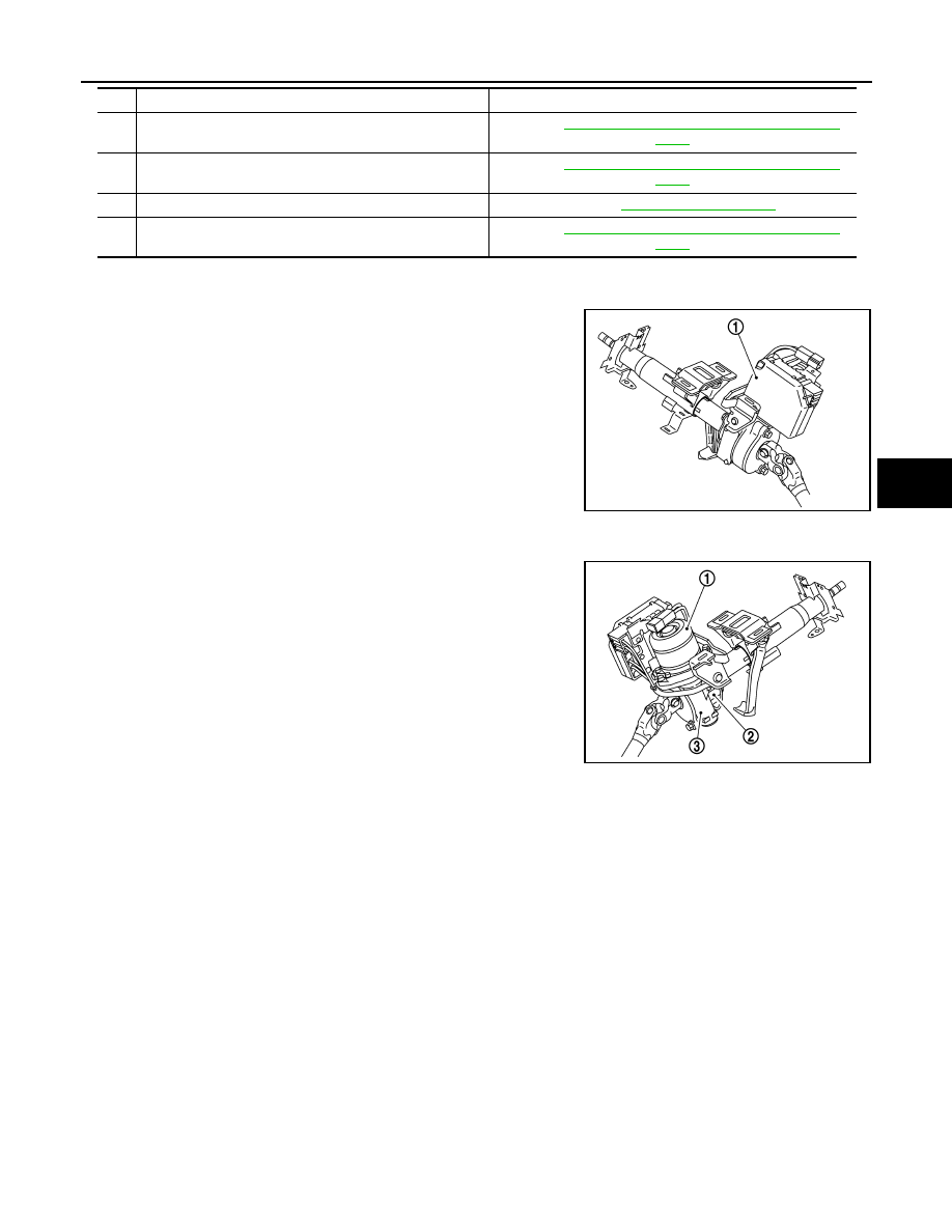
• EPS control unit (1) is installed to steering column assembly.

• EPS control unit performs an arithmetical operation on data, such

as steering wheel turning force (sensor signal) from the torque

sensor, vehicle speed signal, etc. Then it generates an optimum

assist torque signal to the EPS motor according to the driving con-

dition.

• EPS control unit decreases the output signal to EPS motor while

extremely using the power steering function (e.g., full steering)

consecutively for protecting EPS motor and EPS control unit

(Overload protection control).

EPS Motor, Torque Sensor, Reduction Gear

INFOID:0000000009667172

EPS motor (1), torque sensor (2) and reduction gear (3) are installed

to steering column assembly.

EPS MOTOR

EPS motor provides the assist torque by the control signal from EPS control unit.

TORQUE SENSOR

Torque sensor detects the steering torque, and transmits the signal to EPS control unit.

REDUCTION GEAR

Reduction gear increases the assist torque provided from EPS motor with worm gears, and outputs to the col-

umn shaft.

4.

EPS motor

Refer to 

STC-5, "EPS Motor, Torque Sensor, Reduction 

Gear"

.

5.

Reduction gear

Refer to 

STC-5, "EPS Motor, Torque Sensor, Reduction 

Gear"

.

6.

EPS control unit

Refer to 

STC-5, "EPS Control Unit"

.

7.

Torque sensor

Refer to 

STC-5, "EPS Motor, Torque Sensor, Reduction 

Gear"

.

No.

Component

Function

JSGIA0852ZZ

JSGIA0853ZZ

STC-6

< SYSTEM DESCRIPTION >

DIAGNOSIS SYSTEM (EPS CONTROL UNIT)

DIAGNOSIS SYSTEM (EPS CONTROL UNIT)

CONSULT Function

INFOID:0000000009667173

FUNCTION

CONSULT can display each diagnostic item using the diagnostic test modes shown following.

*: The following diagnosis information is erased by erasing.

• DTC

• Freeze frame data (FFD)

ECU IDENTIFICATION

Displays the part number stored in the control unit.

SELF-DIAG RESULTS MODE

Refer to 

STC-10, "DTC Index"

.

When “CRNT” is displayed on self-diagnosis result.

• The system is presently malfunctioning.

When “PAST” is displayed on self-diagnosis result.

• System malfunction in the past is detected, but the system is presently normal.

FREEZE FRAME DATA (FFD)

The following vehicle status is recorded when DTC is detected and is displayed on CONSULT.

DATA MONITOR MODE

*1: Almost in accordance with the value of “MOTOR SIG”. It is not a malfunction though these values are not

accorded when steering quickly.

Diagnostic test mode

Function

ECU identification

The part number stored in the control unit can be read.

Self diagnostic result

Self-diagnostic results and freeze frame data can be read and erased quickly.

*

Data monitor

Input/Output data in the EPS control unit can be read.

Item name

Display item

IGN COUNTER
(0-39)

The number of times that ignition switch is turned ON after the DTC is detected is displayed.
• When “0” is displayed: It indicates that the system is presently malfunctioning.
• When except “0” is displayed: It indicates that system malfunction in the past is detected, but the system is pres-

ently normal.
NOTE:
Each time when ignition switch is turned OFF to ON, numerical number increases in 1

→2→3...38→39.

When the operation number of times exceeds 39, the number does not increase and “39” is displayed until self-
diagnosis is erased.

Monitor item (Unit)

Remarks

BATTERY VOLT (V)

Displays the power supply voltage for EPS control unit.

TORQUE SENSOR (Nm)

Displays steering wheel turning force detected by torque sensor.

MOTOR CURRENT (A)

Displays the current value consumed by EPS motor.

*1

MOTOR SIG (A)

Displays the current commanded value to EPS motor.

ASSIST TORQUE (Nm)

Displays assist torque being output by the electric power steering.

C/U TEMP (

°C or °F )

Displays the temperature of the EPS control unit.

ASSIST LEVEL (%)

Normally displays 100%. In case of an excessive stationary steering, the assist 
curvature gradually falls. However, it return to 100% when left standing.

*2

VEHICLE SPEED (km/h or MPH)

Vehicle speed is displayed from vehicle speed signal via CAN communication.

*3

WARNING LAMP (On/Off)

EPS warning lamp control status is displayed.

ENGINE STATUS (Stop/Run)

Engine speed is displayed from engine status signal via CAN communication.

DIAGNOSIS SYSTEM (EPS CONTROL UNIT)

STC-7

< SYSTEM DESCRIPTION >

C

D

E

F

H

I

J

K

L

M

A

B

STC

N

O

P

*2: Normally displays 100%. In case of an excessive stationary steering, the assist curvature gradually falls.

However, it returns to 100% when left standing.

*3: It is not a malfunction, though it might not be corresponding just after ignition switch in turned ON.

STC-8

< ECU DIAGNOSIS INFORMATION >

EPS CONTROL UNIT

ECU DIAGNOSIS INFORMATION

EPS CONTROL UNIT

Reference Value

INFOID:0000000009667174

VALUES ON THE DIAGNOSIS TOOL

CAUTION:

The output signal indicates the EPS control unit calculation data. The normal values will be displayed

even in the event that the output circuit (harness) is open.

*1: Almost in accordance with the value of “MOTOR SIG”. It is not a malfunction though these values are not

accorded when steering quickly.

*2: A fixed value is indicated regardless of steering turning.

*3: Normally displays 100%. In case of an excessive stationary steering, the assist curvature gradually falls.

However, it returns to 100% when left standing.

*4: It is not a malfunction, though it might not be corresponding just after ignition switch in turned ON.

Monitor item 

Data monitor

Condition

Display value

BATTERY VOLT

Ignition switch: ON

Battery voltage

TORQUE SENSOR

Engine running

Steering wheel: Not steering (There is 
no steering force)

Approx. 0 Nm

Steering wheel: Right turn

Positive value (Nm)

Steering wheel: Left turn

Negative value (Nm)

MOTOR CURRENT

Engine running

Steering wheel: Not steering (There is 
no steering force)

Approx. 0 A

Steering wheel: Right or left turn

Displays consumption current of 
EPS motor (A)

*1

MOTOR SIG

Engine running

Steering wheel: Not steering (There is 
no steering force)

Approx. 0 A

Steering wheel: Right turn

Positive value (A)

Steering wheel: Left turn

Negative value (A)

ASSIST TORQUE

Engine running

Approx. 0 Nm

*2

C/U TEMP

Ignition switch ON or engine running

Displays temperature of inside of 
EPS control unit (

°C or °F)

ASSIST LEVEL

Engine running

100 %

*3

VEHICLE SPEED

Vehicle stopped

0 km/h or mph

While driving

Approximately equal to the indication 
on speedometer

*4

(inside of 

±10%)

WARNING LAMP

EPS warning lamp: ON

On

EPS warning lamp: OFF

Off

ENGINE STATUS

Engine not running

Stop

Engine running

Run


Content   ..  762  763  764  765   ..