Nissan Versa Note. Manual - part 724
B2196 DONGLE UNIT
SEC-175
< DTC/CIRCUIT DIAGNOSIS >
[WITHOUT INTELLIGENT KEY SYSTEM]
C
D
E
F
G
H
I
J
L
M
A
B
SEC
N
O
P
B2196 DONGLE UNIT
Description
INFOID:0000000009521027
BCM performs ID verification between BCM and dongle unit.
When verification result is OK, BCM permits cranking.
DTC Logic
INFOID:0000000009521028
DTC DETECTION LOGIC
DTC CONFIRMATION PROCEDURE
1.
PERFORM DTC CONFIRMATION PROCEDURE
1. Turn ignition switch ON.
2. Turn ignition switch OFF.
3. Turn ignition switch ON.
4. Check DTC in “Self-diagnosis result” mode of “BCM” using CONSULT.
Is the DTC detected?
YES
>> Refer to
SEC-175, "Diagnosis Procedure"
NO
>> Inspection End.
Diagnosis Procedure
INFOID:0000000009521029
Regarding Wiring Diagram information, refer to
1.
PERFORM INITIALIZATION
1. Perform initialization of BCM and registration of all mechanical keys using CONSULT.
For initialization and registration procedures, refer to CONSULT Immobilizer mode and follow the on-
screen instructions
2. Start the engine.
Dose the engine start?
YES
>> Inspection End.
NO
>> GO TO 2.
2.
CHECK DONGLE UNIT CIRCUIT
1. Turn ignition switch OFF.
2. Disconnect BCM connector and dongle unit connector.
3. Check continuity between BCM harness connector and dongle unit harness connector.
4. Check continuity between BCM harness connector and ground.
Is the inspection result normal?
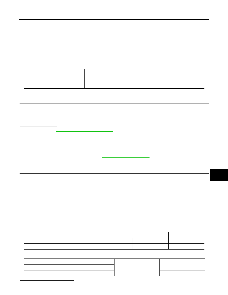
DTC No.
Trouble diagnosis name
DTC detecting condition
Possible cause
B2196
DONGLE NG
The ID verification results between BCM
and dongle unit is NG.
• Harness or connectors
(Dongle unit circuit is open or shorted.)
• Dongle unit
BCM
Dongle unit
Continuity
Connector
Terminal
Connector
Terminal
M18
24
M6
1
Yes
BCM
Ground
Continuity
Connector
Terminal
M18
24
No