Nissan Versa Note. Manual - part 704
B2605 SHIFT POSITION
SEC-95
< DTC/CIRCUIT DIAGNOSIS >
[WITH INTELLIGENT KEY SYSTEM]
C
D
E
F
G
H
I
J
L
M
A
B
SEC
N
O
P
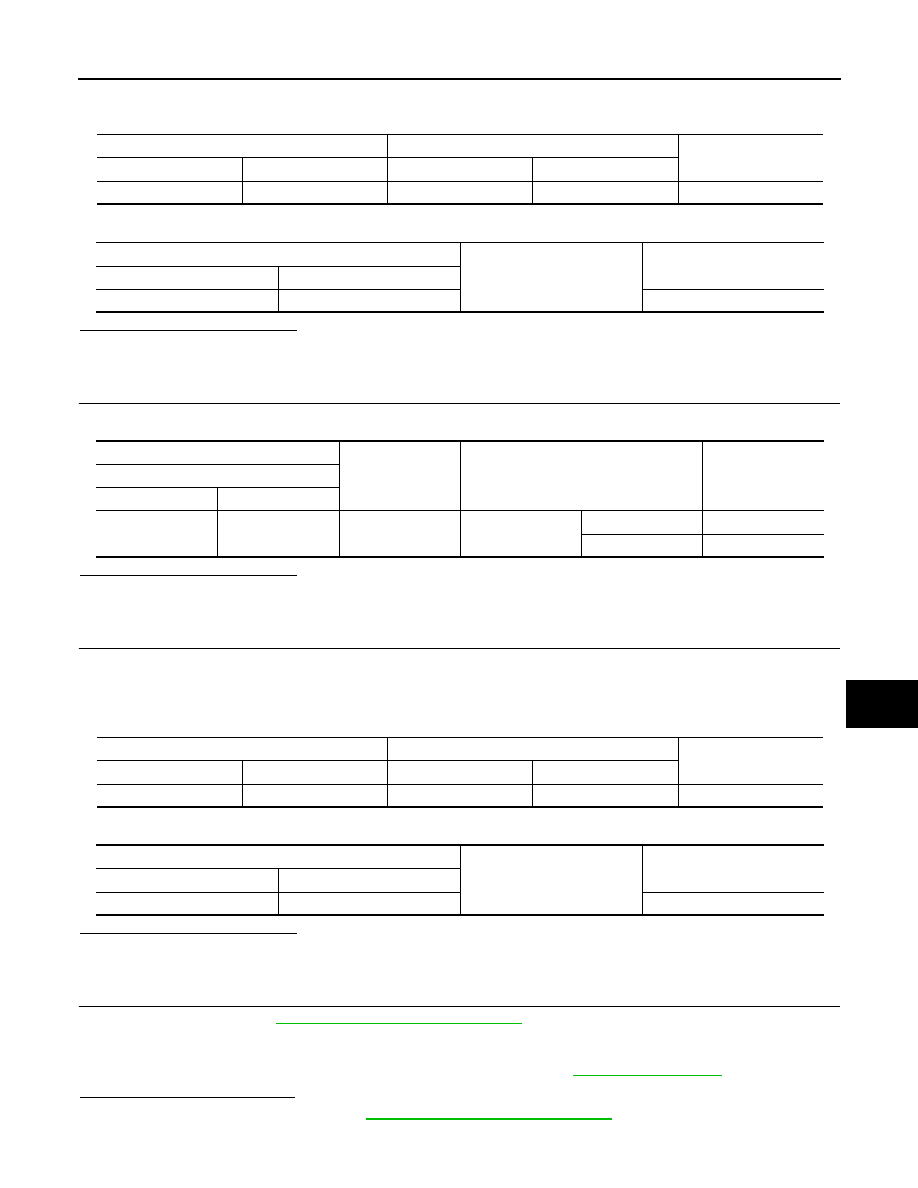
4. Check continuity between IPDM E/R harness connector and transmission range switch harness connec-
tor.
5. Check continuity between IPDM E/R harness connector and ground.
Is the inspection result normal?
YES
>> GO TO 5.
NO
>> Repair or replace harness.
3.
CHECK BCM INPUT SIGNAL
1. Check voltage between BCM harness connector and ground.
Is the inspection result normal?
YES
>> GO TO 5.
NO
>> GO TO 4.
4.
CHECK BCM INPUT SIGNAL CIRCUIT
1. Turn ignition switch OFF.
2. Disconnect BCM connector.
3. Disconnect transmission range switch connector.
4. Check continuity between BCM harness connector and transmission range switch harness connector.
5. Check continuity between IPDM E/R harness connector and ground.
Is the inspection result normal?
YES
>> GO TO 5.
NO
>> Repair or replace harness.
5.
REPLACE BCM
1. Replace BCM. Refer to
BCS-70, "Removal and Installation"
.
2. Perform initialization of BCM using CONSULT. Refer to the CONSULT Immobilizer mode and follow the
on-screen instructions.
3. Perform DTC CONFIRMATION PROCEDURE for B2605. Refer to
Is DTC B2605 detected again?
YES
>> Replace IPDM E/R. Refer to
PCS-31, "Removal and Installation"
.
NO
>> Inspection End.
IPDM E/R
Transmission range switch
Continuity
Connector
Terminal
Connector
Terminal
F42
40
F52
10
Yes
IPDM E/R
Ground
Continuity
Connector
Terminal
F42
40
No
(+)
(–)
Condition
Voltage (V)
(Approx.)
BCM
Connector
Terminal
M98
102
Ground
Selector lever
P or N position
Battery voltage
Other than above
0
BCM
Transmission range switch
Continuity
Connector
Terminal
Connector
Terminal
M98
102
F52
10
Yes
BCM
Ground
Continuity
Connector
Terminal
M98
102
No