Nissan Versa Note. Manual - part 640
PG
BATTERY
PG-67
< REMOVAL AND INSTALLATION >
C
D
E
F
G
H
I
J
K
L
B
A
O
P
N
REMOVAL AND INSTALLATION
BATTERY
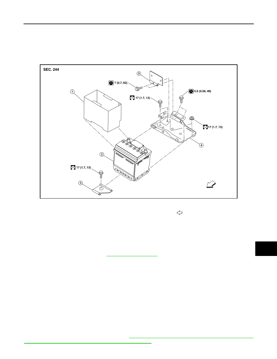
Exploded View
INFOID:0000000008969218
Removal and Installation (Battery)
INFOID:0000000008969219
CAUTION:
To prevent damage to the parts, disconnect the battery cable from the negative terminal first.
REMOVAL
1. Remove the air duct inlet. Refer to
.
2. Disconnect the battery cable from the negative terminal and set aside.
3. Disconnect the battery cable from the positive terminal and set aside.
4. Remove the remove the battery wedge bracket.
5. Remove the battery cover and the battery.
INSTALLATION
Installation is in the reverse order of removal.
CAUTION:
Replace the battery if it has been dropped or sustained and impact.
To install the battery, carefully read the following instructions:
• To prevent damage to the parts, connect the battery cable to the positive terminal first.
• After connecting battery cables, to securely supply battery voltage, ensure that they are tightly
clamped to battery terminals for good contact.
• To securely supply battery voltage, check battery terminal for poor connection caused by corrosion.
Reset electronic systems as necessary. Refer to
PG-64, "ADDITIONAL SERVICE WHEN REMOVING BAT-
TERY NEGATIVE TERMINAL : Special Repair Requirement"
.
AWGIA0296ZZ
1.
Battery cover
2.
Battery
3.
Battery wedge bracket
4.
Battery tray
5.
Battery tray bracket
Front