Nissan Versa Note. Manual - part 583


  Index      Nissan     Nissan Versa Note (2014 year) - Service and Repair Manual


Search            


Content   ..  581  582  583  584   ..


Nissan Versa Note. Manual - part 583


MWI

SYSTEM

MWI-7

< SYSTEM DESCRIPTION >

C

D

E

F

G

H

I

J

K

L

M

B

A

O

P

SYSTEM

METER SYSTEM
METER SYSTEM : System Description

INFOID:0000000009654092
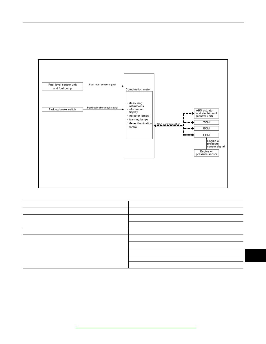
SYSTEM DIAGRAM

COMBINATION METER INPUT SIGNAL (CAN COMMUNICATION SIGNAL)

DESCRIPTION

Combination Meter

• The combination meter receives necessary signals from each unit, switch, and sensor to control the follow-

ing functions.

- Measuring instruments

- Warning lamps

- Indicator lamps

- Meter illumination control

- Information display

• The combination meter incorporates a buzzer function that sounds an audible alarm with the integrated

buzzer device. Refer to 

WCS-6, "WARNING CHIME SYSTEM : System Description"

 for further details.

AWNIA3080GB

Transmit unit

Signal name

ABS actuator and electric unit (control unit)

Vehicle speed signal

BCM

Door switch signal

Buzzer signal

TCM

Shift position signal

ECM

Engine speed signal

Engine coolant temperature signal

Engine oil pressure signal

Fuel consumption signal

Loose fuel cap signal

MWI-8

< SYSTEM DESCRIPTION >

SYSTEM

• The combination meter includes an on board diagnosis function.

• The combination meter can be diagnosed with CONSULT.

METER CONTROL FUNCTION LIST

METER SYSTEM : Fail-safe

INFOID:0000000009654093

The combination meter activates the fail-safe control if CAN communication with each unit is malfunctioning.

System

Description

Reference

Measuring instruments

Speedometer

Indicates vehicle speed.

MWI-9, "SPEED-
OMETER : Sys-
tem Description"

Tachometer

Indicates engine speed.

MWI-9, "TA-
CHOMETER : 
System Descrip-
tion"

Shift position indicator

Indicates shift position.

MWI-10, "SHIFT 
POSITION INDI-
CATOR : System 
Description"

Warning lamp/indicator 
lamp

Engine oil pressure warning lamp

The warning lamp turns ON or turns OFF, 
according to engine hydraulic pressure.

MWI-10, "OIL 
PRESSURE 
WARNING LAMP 
: System Descrip-
tion"

Meter illumination con-
trol

Meter illumination control function

Controls the back light of combination meter.

MWI-10, "METER 
ILLUMINATION 
CONTROL : Sys-
tem Description"

Information display

Odo/trip meter

Indicates mileage.

MWI-11, "INFOR-
MATION DIS-
PLAY : System 
Description"

Engine coolant temperature gauge

Indicates engine coolant temperature.

Fuel gauge

Indicates fuel level.

Loose fuel cap warning

Indicates loose fuel cap.

Low fuel warning

Indicates fuel level.

Trip computer

Instant fuel consumption

Displays current fuel consumption.

Average fuel consumption Displays average fuel consumption.

Distance to empty

Displays distance to empty.

Travel distance

Displays mileage.

Function

Specifications

Speedometer

Reset to zero by suspending communication.

Tachometer

Illumination control

When suspending communication, changes to nighttime mode.

Shift position indicator

When suspending communication, not indicate.

Information display

Trip com-
puter

Current fuel consump-
tion

• When reception time of an abnormal signal is 2 seconds or 

less, the last received datum is used for calculation to indi-
cate the result.

• When reception time of an abnormal signal is more than two 

seconds, the last result calculated during normal condition is 
indicated.

Average fuel consump-
tion

Distance to empty

Engine coolant temperature gauge

Reset to zero by suspending communication.

Odo/trip meter

An indicated value is maintained at communications blackout.

Buzzer

The buzzer turns OFF by suspending communication.

MWI

SYSTEM

MWI-9

< SYSTEM DESCRIPTION >

C

D

E

F

G

H

I

J

K

L

M

B

A

O

P

SPEEDOMETER
SPEEDOMETER : System Description

INFOID:0000000009654094

SYSTEM DIAGRAM

DESCRIPTION

The ABS actuator and electric unit (control unit) receives each wheel speed sensor signal and provides a vehi-

cle speed signal to the combination meter via CAN communication.

TACHOMETER
TACHOMETER : System Description

INFOID:0000000009654095

SYSTEM DIAGRAM

DESCRIPTION

The crank position sensor sends a crankshaft position signal to the ECM. The ECM provides an engine speed

signal to the combination meter via CAN communication lines. The tachometer indicates engine speed in rev-

olutions per minute (rpm).

SHIFT POSITION INDICATOR

Warning lamp/indicator lamp

ABS warning lamp

The lamp turns ON by suspending communication.

Malfunction indicator lamp (MIL)

EPS warning lamp

Brake warning lamp

High beam indicator lamp

The lamp turns OFF by suspending communication.

Turn signal indicator lamp

Door warning lamp

Light indicator lamp

Engine oil pressure warning lamp

Key warning lamp

O/D OFF indicator lamp

Shift P warning lamp

Engine start operation indicator lamp

Function

Specifications

AWNIA2379GB

JSNIA2462GB

MWI-10

< SYSTEM DESCRIPTION >

SYSTEM

SHIFT POSITION INDICATOR : System Description

INFOID:0000000009654096

SYSTEM DIAGRAM

DESCRIPTION

The combination meter receives the shift position signal from TCM via CAN communication, and displays the

position of the shift indicator.

OIL PRESSURE WARNING LAMP
OIL PRESSURE WARNING LAMP : System Description

INFOID:0000000009654097

SYSTEM DIAGRAM

DESCRIPTION

The combination meter turns the engine oil pressure warning lamp ON when receiving a signal from the ECM

via CAN communication.

METER ILLUMINATION CONTROL
METER ILLUMINATION CONTROL : System Description

INFOID:0000000009654098

SYSTEM DIAGRAM

DESCRIPTION

• Combination meter controls meter illumination, based on the following signal.

- Position light request signal

• The combination meter turns ON meter illumination when the following conditions are satisfied.

AWNIA3081GB

AWNIA2885GB

JSNIA2919GB

Condition

Combination switch (Lighting switch)

1st or 2nd position


Content   ..  581  582  583  584   ..