Nissan Versa Note. Manual - part 538


  Index      Nissan     Nissan Versa Note (2014 year) - Service and Repair Manual


Search            


Content   ..  536  537  538  539   ..


Nissan Versa Note. Manual - part 538


IP-26

< REMOVAL AND INSTALLATION >

UPPER GLOVE BOX

UPPER GLOVE BOX

Removal and Installation

INFOID:0000000009667766
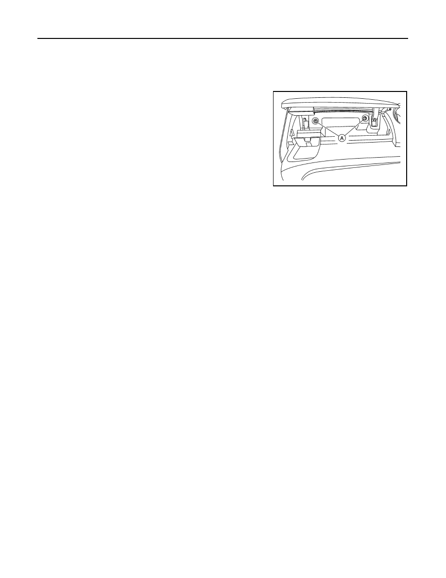
REMOVAL

1. Remove upper glove box screws (A).

2. Release the clips and pawls using a suitable tool and remove upper glove box.

INSTALLATION

Installation is in the reverse order of removal.

ALJIA1253ZZ

LAN

LAN-1

ELECTRICAL & POWER CONTROL

C

D

E

F

G

H

I

J

K

L

B

SECTION 

LAN

A

O

P

N

CONTENTS

LAN SYSTEM

CAN FUNDAMENTAL

HOW TO USE THIS MANUAL ......................

4

HOW TO USE THIS SECTION ............................

4

Information ................................................................

4

PRECAUTION ...............................................

5

PRECAUTIONS ...................................................

5

Precautions for Trouble Diagnosis  ............................

5

Precautions for Harness Repair ................................

5

SYSTEM DESCRIPTION  ..............................

6

SYSTEM ..............................................................

6

CAN COMMUNICATION SYSTEM .............................

6

CAN COMMUNICATION SYSTEM : System De-
scription ...................................................................
..

6

DIAG ON CAN  .............................................................

6

DIAG ON CAN : System Description  ........................

6

TROUBLE DIAGNOSIS  ......................................

8

Component Description .............................................

8

Condition of Error Detection ......................................

8

Symptom When Error Occurs in CAN Communi-
cation System ..........................................................
..

9

CAN Diagnosis with CONSULT  ..............................

11

Self-Diagnosis .........................................................

12

CAN Diagnostic Support Monitor  ............................

12

How to Use CAN Communication Signal Chart  ......

14

BASIC INSPECTION  ...................................

15

DIAGNOSIS AND REPAIR WORKFLOW  .........

15

Trouble Diagnosis Flow Chart .................................

15

Trouble Diagnosis Procedure ..................................

15

CAN

HOW TO USE THIS MANUAL .....................

20

HOW TO USE THIS SECTION  .........................

20

Information ...............................................................

20

Abbreviation List ......................................................

20

PRECAUTION ..............................................

21

PRECAUTIONS .................................................

21

Precaution for Supplemental Restraint System 
(SRS) "AIR BAG" and "SEAT BELT PRE-TEN-
SIONER" .................................................................

21

Precautions for Trouble Diagnosis  ..........................

21

Precautions for Harness Repair  ..............................

21

SYSTEM DESCRIPTION  .............................

23

COMPONENT PARTS  ......................................

23

Component Parts Location  ......................................

23

SYSTEM ............................................................

24

CAN COMMUNICATION SYSTEM ............................

24

CAN COMMUNICATION SYSTEM : System De-
scription ...................................................................

24

CAN COMMUNICATION SYSTEM : CAN Com-
munication Control Circuit  .......................................

27

CAN COMMUNICATION SYSTEM : CAN System 
Specification Chart  ..................................................

28

CAN COMMUNICATION SYSTEM : CAN Com-
munication Signal Chart  ..........................................

29

WIRING DIAGRAM ......................................

32

CAN SYSTEM  ...................................................

32

Wiring Diagram ........................................................

32

BASIC INSPECTION  ...................................

38

DIAGNOSIS AND REPAIR WORKFLOW  ........

38

Interview Sheet ........................................................

38

DTC/CIRCUIT DIAGNOSIS  .........................

39

MALFUNCTION AREA CHART ........................

39

LAN-2

Main Line  ................................................................

39

Branch Line  ............................................................

39

Short Circuit ............................................................

39

MAIN LINE BETWEEN IPDM-E AND DLC 
CIRCUIT .............................................................

40

Diagnosis Procedure  ..............................................

40

MAIN LINE BETWEEN IPDM-E AND AVM 
CIRCUIT .............................................................

41

Diagnosis Procedure  ..............................................

41

MAIN LINE BETWEEN AVM AND DLC CIR-
CUIT ...................................................................

42

Diagnosis Procedure  ..............................................

42

ECM BRANCH LINE CIRCUIT  ..........................

43

Diagnosis Procedure  ..............................................

43

ABS BRANCH LINE CIRCUIT  ..........................

44

Diagnosis Procedure  ..............................................

44

IPDM-E BRANCH LINE CIRCUIT  .....................

45

Diagnosis Procedure  ..............................................

45

TCM BRANCH LINE CIRCUIT  ..........................

46

Diagnosis Procedure  ..............................................

46

AVM BRANCH LINE CIRCUIT  ..........................

47

Diagnosis Procedure  ..............................................

47

A-BAG BRANCH LINE CIRCUIT  ......................

48

Diagnosis Procedure  ..............................................

48

AV BRANCH LINE CIRCUIT  .............................

49

Diagnosis Procedure  ..............................................

49

DLC BRANCH LINE CIRCUIT ...........................

50

Diagnosis Procedure  ..............................................

50

EPS BRANCH LINE CIRCUIT ...........................

51

Diagnosis Procedure  ..............................................

51

M&A BRANCH LINE CIRCUIT ..........................

52

Diagnosis Procedure  ..............................................

52

STRG BRANCH LINE CIRCUIT  ........................

53

Diagnosis Procedure  ..............................................

53

BCM BRANCH LINE CIRCUIT ..........................

54

Diagnosis Procedure  ..............................................

54

CAN COMMUNICATION CIRCUIT ....................

55

Diagnosis Procedure  ..............................................

55

CAN SYSTEM (TYPE 501)

DTC/CIRCUIT DIAGNOSIS .........................

57

MAIN LINE BETWEEN IPDM-E AND DLC 
CIRCUIT .............................................................

57

Diagnosis Procedure  ..............................................

57

ECM BRANCH LINE CIRCUIT  ..........................

58

Diagnosis Procedure ...............................................

58

ABS BRANCH LINE CIRCUIT  ..........................

59

Diagnosis Procedure ...............................................

59

IPDM-E BRANCH LINE CIRCUIT  .....................

60

Diagnosis Procedure ...............................................

60

A-BAG BRANCH LINE CIRCUIT  ......................

61

Diagnosis Procedure ...............................................

61

DLC BRANCH LINE CIRCUIT  ..........................

62

Diagnosis Procedure ...............................................

62

EPS BRANCH LINE CIRCUIT ...........................

63

Diagnosis Procedure ...............................................

63

M&A BRANCH LINE CIRCUIT ..........................

64

Diagnosis Procedure ...............................................

64

STRG BRANCH LINE CIRCUIT ........................

65

Diagnosis Procedure ...............................................

65

BCM BRANCH LINE CIRCUIT ..........................

66

Diagnosis Procedure ...............................................

66

CAN COMMUNICATION CIRCUIT  ...................

67

Diagnosis Procedure ...............................................

67

CAN SYSTEM (TYPE 502)

DTC/CIRCUIT DIAGNOSIS ........................

69

MAIN LINE BETWEEN IPDM-E AND DLC 
CIRCUIT .............................................................

69

Diagnosis Procedure ...............................................

69

ECM BRANCH LINE CIRCUIT ..........................

70

Diagnosis Procedure ...............................................

70

ABS BRANCH LINE CIRCUIT  ..........................

71

Diagnosis Procedure ...............................................

71

IPDM-E BRANCH LINE CIRCUIT  .....................

72

Diagnosis Procedure ...............................................

72

TCM BRANCH LINE CIRCUIT  ..........................

73

Diagnosis Procedure ...............................................

73

A-BAG BRANCH LINE CIRCUIT  ......................

74

Diagnosis Procedure ...............................................

74

DLC BRANCH LINE CIRCUIT  ..........................

75

Diagnosis Procedure ...............................................

75

EPS BRANCH LINE CIRCUIT ...........................

76

Diagnosis Procedure ...............................................

76

M&A BRANCH LINE CIRCUIT ..........................

77

Diagnosis Procedure ...............................................

77

STRG BRANCH LINE CIRCUIT ........................

78

Diagnosis Procedure ...............................................

78

BCM BRANCH LINE CIRCUIT ..........................

79

LAN

LAN-3

C

D

E

F

G

H

I

J

K

L

B

A

O

P

N

Diagnosis Procedure ...............................................

79

CAN COMMUNICATION CIRCUIT  ....................

80

Diagnosis Procedure ...............................................

80

CAN SYSTEM (TYPE 503)

DTC/CIRCUIT DIAGNOSIS  .........................

82

MAIN LINE BETWEEN IPDM-E AND AVM 
CIRCUIT .............................................................

82

Diagnosis Procedure ...............................................

82

MAIN LINE BETWEEN AVM AND DLC CIR-
CUIT ....................................................................

83

Diagnosis Procedure ...............................................

83

ECM BRANCH LINE CIRCUIT ...........................

84

Diagnosis Procedure ...............................................

84

ABS BRANCH LINE CIRCUIT  ...........................

85

Diagnosis Procedure ...............................................

85

IPDM-E BRANCH LINE CIRCUIT  ......................

86

Diagnosis Procedure ...............................................

86

TCM BRANCH LINE CIRCUIT ...........................

87

Diagnosis Procedure ...............................................

87

AVM BRANCH LINE CIRCUIT  .........................

88

Diagnosis Procedure  ...............................................

88

A-BAG BRANCH LINE CIRCUIT ......................

89

Diagnosis Procedure  ...............................................

89

AV BRANCH LINE CIRCUIT  ............................

90

Diagnosis Procedure  ...............................................

90

DLC BRANCH LINE CIRCUIT  ..........................

91

Diagnosis Procedure  ...............................................

91

EPS BRANCH LINE CIRCUIT  ..........................

92

Diagnosis Procedure  ...............................................

92

M&A BRANCH LINE CIRCUIT  .........................

93

Diagnosis Procedure  ...............................................

93

STRG BRANCH LINE CIRCUIT  .......................

94

Diagnosis Procedure  ...............................................

94

BCM BRANCH LINE CIRCUIT  .........................

95

Diagnosis Procedure  ...............................................

95

CAN COMMUNICATION CIRCUIT  ...................

96

Diagnosis Procedure  ...............................................

96


Content   ..  536  537  538  539   ..