Nissan Versa Note. Manual - part 509


  Index      Nissan     Nissan Versa Note (2014 year) - Service and Repair Manual


Search            


Content   ..  507  508  509  510   ..


Nissan Versa Note. Manual - part 509


INL-4

< PREPARATION >

PREPARATION

PREPARATION

PREPARATION

Special Service Tool

INFOID:0000000009445810

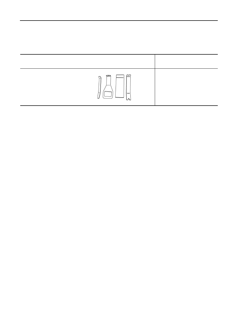
The actual shapes of Kent-Moore tools may differ from those of special service tools illustrated here.

Tool number
(Kent-Moore No.)
Tool name

Description 

  —
(J-46534)
Trim Tool Set

Removing trim components

AWJIA0483ZZ

COMPONENT PARTS

INL-5

< SYSTEM DESCRIPTION >

C

D

E

F

G

H

I

J

K

M

A

B

INL

N

O

P

SYSTEM DESCRIPTION

COMPONENT PARTS

Component Parts Location

INFOID:0000000009642980

No.

Part

Description

1.

Cargo lamp

Refer to 

INL-57, "Bulb Specifications"

.

2.

Interior room lamp

Refer to 

INL-57, "Bulb Specifications"

.

3.

Map lamp

Refer to 

INL-57, "Bulb Specifications"

.

4.

IPDM E/R

Controls the integrated relay according to the request signal from BCM. Refer to 

PCS-

5, "Component Parts Location"

 (with Intelligent Key) or 

PCS-34, "Component Parts Lo-

cation"

 (without Intelligent Key) for detailed installation location.

ALLIA1325ZZ

INL-6

< SYSTEM DESCRIPTION >

COMPONENT PARTS

5.

BCM

• Activates the interior room lamp timer depending on the vehicle condition to turn the 

interior room lamps ON/OFF.

• Operates the interior room lamp battery saver depending on the vehicle condition to 

cut the interior room lamp power supply. 

• Detects each switch condition by the combination switch reading function.
• Judges the illumination lamp ON/OFF status depending on the vehicle condition. 

And then it transmits position light request signal to IPDM E/R and combination 
meter (with CAN communication). 

Refer to 

BCS-6, "BODY CONTROL SYSTEM : Component Parts Location"

 (with Intel-

ligent Key) or 

BCS-73, "BODY CONTROL SYSTEM : Component Parts Location"


(without Intelligent Key) for detailed installation location.

6.

Back door switch

Refer to 

DLK-18, "INTELLIGENT KEY SYSTEM : Back Door Lock Assembly"

 (with In-

telligent Key) or 

DLK-189, "REMOTE KEYLESS ENTRY SYSTEM : Back Door Lock 

Assembly"

 (without Intelligent Key).

7.

Push-button ignition switch

Refer to 

PCS-64, "POWER DISTRIBUTION SYSTEM : System Description"

.

8.

Combination switch

Refer to 

EXL-6, "Component Parts Location"

 (with Intelligent Key) or 

EXL-6, "Compo-

nent Parts Location"

 (without Intelligent Key).

9.

Combination meter

Receives the dimmer signal from BCM. Refer to 

MWI-10, "METER ILLUMINATION 

CONTROL : System Description"

.

10.

Audio unit (without navigation)
AV control unit (with navigation)

Receives the dimmer signal from BCM. Refer to 

AV-8, "Audio unit"

 (base audio)

AV-

66, "Audio Unit"

 (display audio) or 

AV-134, "AV Control Unit"

 (navigation).

11.

Front door switch LH (RH side similar)

Refer to 

DLK-19, "INTELLIGENT KEY SYSTEM : Door Switch"

 (with Intelligent Key) 

or 

DLK-189, "REMOTE KEYLESS ENTRY SYSTEM : Door Switch"

 (without Intelligent 

Key).

12.

Rear door switch LH (RH side similar)

Refer to 

DLK-19, "INTELLIGENT KEY SYSTEM : Door Switch"

 (with Intelligent Key) 

or 

DLK-189, "REMOTE KEYLESS ENTRY SYSTEM : Door Switch"

 (without Intelligent 

Key).

No.

Part

Description

SYSTEM

INL-7

< SYSTEM DESCRIPTION >

C

D

E

F

G

H

I

J

K

M

A

B

INL

N

O

P

SYSTEM

INTERIOR ROOM LAMP CONTROL SYSTEM
INTERIOR ROOM LAMP CONTROL SYSTEM : System Description

INFOID:0000000009642982

SYSTEM DIAGRAM (WITH INTELLIGENT KEY)

ALLIA1326GB


Content   ..  507  508  509  510   ..