Nissan Versa Note. Manual - part 508
HRN-6
< REMOVAL AND INSTALLATION >
HORN
REMOVAL AND INSTALLATION
HORN
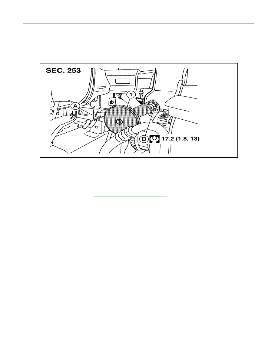
Exploded View
INFOID:0000000009486773
Removal and Installation
INFOID:0000000009486774
REMOVAL
1. Remove front grille. Refer to
EXT-29, "Removal and Installation"
2. Disconnect the harness connectors from the horn.
3. Remove horn nut and the horn.
INSTALLATION
Installation is in the reverse order of removal.
1. Horn
A. Connector
B. Nut
AWLIA2176ZZ