Nissan Versa Note. Manual - part 492


  Index      Nissan     Nissan Versa Note (2014 year) - Service and Repair Manual


Search            


Content   ..  490  491  492  493   ..


Nissan Versa Note. Manual - part 492


PRECAUTIONS

HAC-3

< PRECAUTION >

[MANUAL AIR CONDITIONING]

C

D

E

F

G

H

J

K

L

M

A

B

HAC

N

O

P

PRECAUTION

PRECAUTIONS

Precaution for Supplemental Restraint System (SRS) "AIR BAG" and "SEAT BELT 
PRE-TENSIONER"

INFOID:0000000009515765

The Supplemental Restraint System such as “AIR BAG” and “SEAT BELT PRE-TENSIONER”, used along

with a front seat belt, helps to reduce the risk or severity of injury to the driver and front passenger for certain

types of collision. Information necessary to service the system safely is included in the SR and SB section of

this Service Manual.

WARNING:

• To avoid rendering the SRS inoperative, which could increase the risk of personal injury or death in

the event of a collision which would result in air bag inflation, all maintenance must be performed by

an authorized NISSAN/INFINITI dealer.

• Improper maintenance, including incorrect removal and installation of the SRS, can lead to personal

injury caused by unintentional activation of the system. For removal of Spiral Cable and Air Bag

Module, see the SR section.

• Do not use electrical test equipment on any circuit related to the SRS unless instructed to in this

Service Manual. SRS wiring harnesses can be identified by yellow and/or orange harnesses or har-

ness connectors.

PRECAUTIONS WHEN USING POWER TOOLS (AIR OR ELECTRIC) AND HAMMERS

WARNING:

• When working near the Airbag Diagnosis Sensor Unit or other Airbag System sensors with the Igni-

tion ON or engine running, DO NOT use air or electric power tools or strike near the sensor(s) with a

hammer. Heavy vibration could activate the sensor(s) and deploy the air bag(s), possibly causing

serious injury.

• When using air or electric power tools or hammers, always switch the Ignition OFF, disconnect the

battery and wait at least three minutes before performing any service.

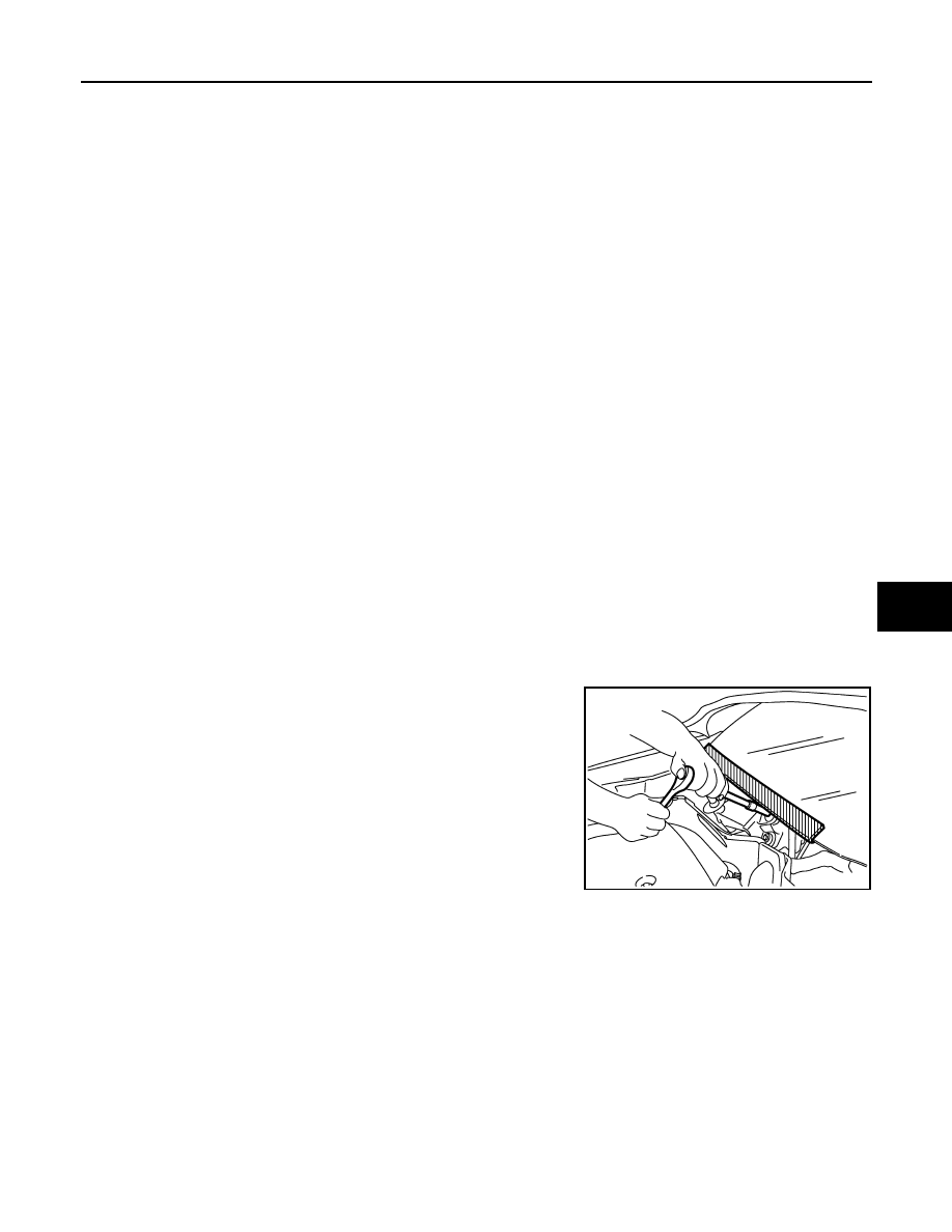
Precaution for Procedure without Cowl Top Cover

INFOID:0000000009515766

When performing the procedure after removing cowl top cover, cover

the lower end of windshield with urethane, etc to prevent damage to

windshield.

Precaution for Work

INFOID:0000000009643768

• When removing or disassembling each component, be careful not to damage or deform it. If a component

may be subject to interference, be sure to protect it with a shop cloth.

• When removing (disengaging) components with a screwdriver or similar tool, be sure to wrap the component

with a shop cloth or vinyl tape to protect it.

• Protect the removed parts with a shop cloth and prevent them from being dropped.

• Replace a deformed or damaged clip.

• If a part is specified as a non-reusable part, always replace it with a new one.

• Be sure to tighten bolts and nuts securely to the specified torque.

• After installation is complete, be sure to check that each part works properly.

• Follow the steps below to clean components:

- Water soluble dirt:

• Dip a soft cloth into lukewarm water, wring the water out of the cloth and wipe the dirty area.

• Then rub with a soft, dry cloth.

- Oily  dirt:

PIIB3706J

HAC-4

< PRECAUTION >

[MANUAL AIR CONDITIONING]

PRECAUTIONS

• Dip a soft cloth into lukewarm water with mild detergent (concentration: within 2 to 3%) and wipe the dirty

area.

• Then dip a cloth into fresh water, wring the water out of the cloth and wipe the detergent off.

• Then rub with a soft, dry cloth.

- Do not use organic solvent such as thinner, benzene, alcohol or gasoline.

- For genuine leather seats, use a genuine leather seat cleaner.

Precautions For Refrigerant System Service

INFOID:0000000009515767

GENERAL REFRIGERANT PRECAUTION

WARNING:

• Do not breathe A/C refrigerant and oil vapor or mist. Exposure may irritate eyes, nose and throat.

Use only approved recovery/recycling equipment to discharge HFC-134a (R-134a) refrigerant. Venti-

late work area before resuming service if accidental system discharge occurs. Additional health and

safety information may be obtained from refrigerant and oil manufacturers.

• Do not release refrigerant into the air. Use approved recovery/recycling recharging equipment to

capture the refrigerant each time an air conditioning system is discharged.

• Wear always eye and hand protection (goggles and gloves) when working with any refrigerant or air

conditioning system.

• Do not store or heat refrigerant containers above 52

°C (126°F).

• Do not heat a refrigerant container with an open flame. Place the bottom of the container in a pail of

warm water if container warming is required.

• Do not intentionally drop, puncture, or incinerate refrigerant containers.

• Keep refrigerant away from open flames. Poisonous gas is produced if refrigerant burns.

• Refrigerant displaces oxygen, therefore be certain to work in well ventilated areas to prevent suffo-

cation.

• Do not pressure test or leakage test HFC-134a (R-134a) service equipment and/or vehicle air condi-

tioning systems with compressed air during repair. Some mixtures of air and HFC-134a (R-134a)

have been shown to be combustible at elevated pressures. These mixtures, if ignited, may cause

injury or property damage. Additional health and safety information may be obtained from refriger-

ant manufacturers.

WORKING WITH HFC-134a (R-134a)

CAUTION:

• CFC-12 (R-12) refrigerant and HFC-134a (R-134a) refrigerant are not compatible. These refrigerants

must never be mixed, even in the smallest amounts. Compressor malfunction is likely occur if the

refrigerants are mixed.

• Use only specified oil for the HFC-134a (R-134a) A/C system and HFC-134a (R-134a) components.

Compressor malfunction is likely to occur if oil other than that specified is used.

• The specified HFC-134a (R-134a) oil rapidly absorbs moisture from the atmosphere. The following

handling precautions must be observed:

- Cap (seal) immediately the component to minimize the entry of moisture from the atmosphere when

removing refrigerant components from a vehicle.

- Do not remove the caps (unseal) until just before connecting the components when installing refrig-

erant components to a vehicle. Connect all refrigerant loop components as quickly as possible to

minimize the entry of moisture into system.

- Use only the specified oil from a sealed container. Reseal immediately containers of oil. Oil becomes

moisture saturated and should not be used without proper sealing.

- Do not allow oil (A/C System Oil Type: DH-PR) to come in contact with styrene foam parts. Damage

may result.

REFRIGERANT CONNECTION

A new type refrigerant connection has been introduced to all refrigerant lines except the following location.

• Expansion valve to evaporator

• Refrigerant pressure sensor to liquid tank

WARNING:

Check that all refrigerant is discharged into the recycling equipment and the pressure in the system is

less than atmospheric pressure. Then gradually loosen the discharge side hose fitting and remove it.

CAUTION:

Observe the following when replacing or cleaning refrigerant cycle components.

PRECAUTIONS

HAC-5

< PRECAUTION >

[MANUAL AIR CONDITIONING]

C

D

E

F

G

H

J

K

L

M

A

B

HAC

N

O

P

• When the compressor is removed, store it in the same way as it is when mounted on the vehicle.

Failure to do so will cause oil to enter the low-pressure chamber.

• Use always a torque wrench and a back-up wrench when connecting tubes.

• Plug immediately all openings to prevent entry of dust and moisture after disconnecting tubes.

• Connect the pipes at the final stage of the operation when installing an air conditioner in the vehicle.

Do not remove the seal caps of pipes and other components until just before required for connec-

tion.

• Allow components stored in cool areas to warm to working area temperature before removing seal

caps. This prevents condensation from forming inside A/C components.

• Remove thoroughly moisture from the refrigeration system before charging the refrigerant.

• Replace always used O-rings.

• Apply oil to the O-rings shown in illustrations when connecting tubes. Be careful not to apply oil to

threaded portion.

• O-ring must be closely attached to the groove portion of tube.

• Be careful not to damage O-ring and tube when replacing the O-ring.

• Connect tube until a click can be heard. Then tighten the nut or bolt by hand. Check that the O-ring is

installed to tube correctly.

• Perform leak test and make sure there are no leaks from connections after connecting lines. Discon-

nect that line and replace the O-ring when the refrigerant leak point is found. Then tighten connec-

tions of seal seat to the specified torque.

COMPRESSOR

CAUTION:

• Plug all openings to prevent moisture and foreign matter from entering.

• When the compressor is removed, store it in the same way as it is when mounted on the vehicle.

• Follow “MAINTENANCE OF OIL LEVEL” exactly when replacing or repairing compressor. Refer to

HA-21, "Description"

.

• Keep friction surfaces between clutch and pulley clean. Wipe them off by using a clean waste cloth

moistened with solvent if the surfaces are contaminated with oil.

• Turn the compressor shaft by hand more than five turns in both directions after compressor service

operation. This equally distributes oil inside the compressor. Let the engine idle and operate the

compressor for one hour after the compressor is installed.

• After replacing the compressor magnet clutch, apply voltage to the new clutch to check for normal

operation.

LEAK DETECTION DYE

CAUTION:

• The A/C system contains a fluorescent leak detection dye used for locating refrigerant leaks. An

ultraviolet (UV) lamp is required to illuminate the dye when inspecting for leaks.

• Always wear fluorescence enhancing UV safety goggles to protect eyes and enhance the visibility of

the fluorescent dye.

Name

: A/C System Oil Type: DH-PR 

RHA861F

HAC-6

< PRECAUTION >

[MANUAL AIR CONDITIONING]

PRECAUTIONS

• The fluorescent leak detection dye is not a replacement for an electronic leak detector. The fluores-

cent leak detection dye should be used in conjunction with an electronic leak detector to pin-point

refrigerant leaks.

• Read and follow all manufacture’s operating instructions and precautions prior to performing the

work for the purpose of safety and customer’s satisfaction.

• A compressor shaft seal should not necessarily be repaired because of dye seepage. The compres-

sor shaft seal should only be repaired after confirming the leak with an electronic leak detector.

• Always remove any remaining dye from the leak area after repairs are completed to avoid a misdiag-

nosis during a future service.

• Do not allow dye to come into contact with painted body panels or interior components. Clean imme-

diately with the approved dye cleaner if dye is spilled. Fluorescent dye left on a surface for an

extended period of time cannot be removed.

• Do not spray the fluorescent dye cleaning agent on hot surfaces (engine exhaust manifold, etc.).

• Do not use more than one refrigerant dye bottle [1/4 ounce (7.4 cc)] per A/C system.

• Leak detection dyes for HFC-134a (R-134a) and CFC-12 (R-12) A/C systems are different. Do not use

HFC-134a (R-134a) leak detection dye in CFC-12 (R-12) A/C system, or CFC-12 (R-12) leak detection

dye in HFC-134a (R-134a) A/C system, or A/C system damage may result.

• The fluorescent properties of the dye remains for three or more years unless a compressor malfunc-

tion occurs.

NOTE:

Identification

• Vehicles with factory installed fluorescent dye have a green label.

• Vehicles without factory installed fluorescent dye have a blue label.

Service Equipment

INFOID:0000000009515768

RECOVERY/RECYCLING RECHARGING EQUIPMENT

Be certain to follow the manufacturer’s instructions for machine operation and machine maintenance. Do not

introduce any refrigerant other than that specified into the machine.

ELECTRICAL LEAK DETECTOR

Be certain to follow the manufacturer’s instructions for tester operation and tester maintenance.

VACUUM PUMP

The oil contained inside the vacuum pump is not compatible with the

specified oil for HFC-134a (R-134a) A/C systems. The vent side of

the vacuum pump is exposed to atmospheric pressure. Vacuum

pump oil may migrate out of the pump into the service hose. This is

possible when the pump is switched OFF after evacuation (vacuum-

ing) and hose is connected to it.

To prevent this migration, use a manual valve placed near the hose-

to-pump connection, as per the following.

• Vacuum pumps usually have a manual isolator valve as part of the

pump. Close this valve to isolate the service hose from the pump.

• Use a hose equipped with a manual shut-off valve near the pump

end for pumps without an isolator. Close the valve to isolate the

hose from the pump.

• Disconnect the hose from the pump if the hose has an automatic

shut-off valve. As long as the hose is connected, the valve is open

and lubricating oil may migrate.

Some one-way valves open when vacuum is applied and close

under no vacuum condition. Such valves may restrict the pump’s

ability to pull a deep vacuum and are not recommended.

MANIFOLD GAUGE SET

RHA270DA


Content   ..  490  491  492  493   ..