Nissan Versa Note. Manual - part 459


  Index      Nissan     Nissan Versa Note (2014 year) - Service and Repair Manual


Search            


Content   ..  457  458  459  460   ..


Nissan Versa Note. Manual - part 459


FRONT STABILIZER

FSU-13

< REMOVAL AND INSTALLATION >

C

D

F

G

H

I

J

K

L

M

A

B

FSU

N

O

P

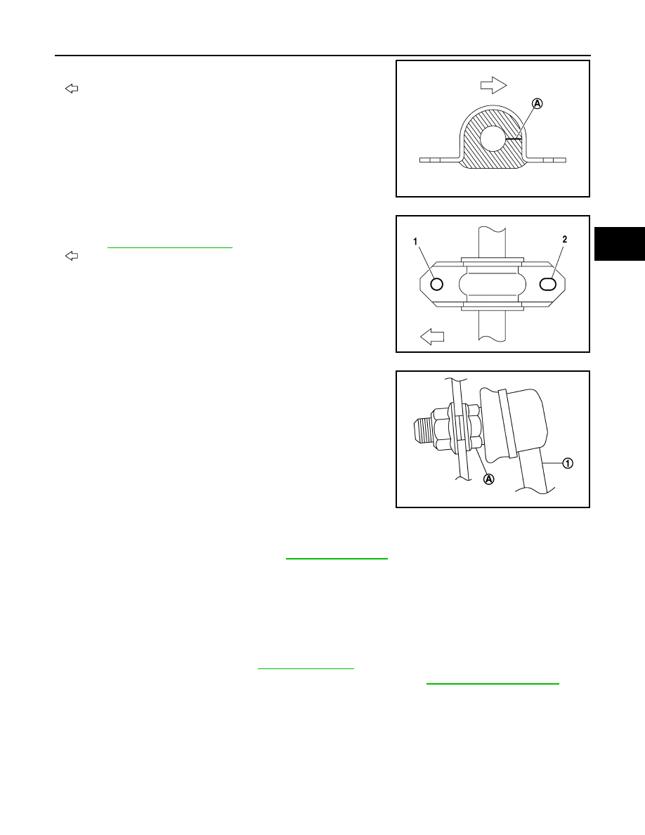
• Install the stabilizer bushing with the slit (A) facing the rear of the

vehicle.

: Rear

• To install stabilizer clamp bolt, temporarily tighten them in numeri-

cal order as shown, then tighten them to the specified torque.

Refer to 

FSU-12, "Exploded View"

.

: Front

• To connect the stabilizer connecting rod (1), tighten the nut while

holding the hexagonal part (A) on the stabilizer connecting rod.

• Perform final tightening of bolts and nuts with the vehicle under unladen conditions with tires on level

ground.

• Perform inspection after installation. Refer to 

FSU-13, "Inspection"

.

Inspection

INFOID:0000000009643756

INSPECTION AFTER REMOVAL

Check the stabilizer bar, the stabilizer connecting rod, the stabilizer bushing, and the stabilizer clamp for defor-

mation, cracks, or damage. Replace components if necessary.

INSPECTION AFTER INSTALLATION

1. Check the wheel alignment. Refer to 

FSU-7, "Inspection"

.

2. Perform the steering angle sensor neutral position adjustment. Refer to 

BRC-53, "Work Procedure"

.

JPEIA0273ZZ

JPEIA0274ZZ

JPEIA0252ZZ

FSU-14

< UNIT REMOVAL AND INSTALLATION >

FRONT SUSPENSION MEMBER

UNIT REMOVAL AND INSTALLATION

FRONT SUSPENSION MEMBER

Exploded View

INFOID:0000000009561131

Removal and Installation

INFOID:0000000009561132

REMOVAL

1. Remove the wheel and tire using power tool. Refer to 

WT-45, "Removal and Installation"

.

2. Disconnect steering outer sockets from steering knuckles. Refer to 

ST-14, "Exploded View"

.

3. Disconnect transverse links from steering knuckle. Refer to

FSU-10, "Exploded View"

.

4. Disconnect stabilizer connecting rods from stabilizer bar. Refer to 

FSU-12, "Exploded View"

.

5. Disconnect the lower joint from the steering gear. Refer to 

ST-12, "Exploded View"

.

6. Set suitable jack under front suspension member.

CAUTION:

Do not damage the front suspension member with suitable jack.

7. Remove the engine rear torque rod. Refer to 

EM-85, "Exploded View"

.

8. Remove suspension member bolts.
9. Gradually lower the jack to remove front suspension member from vehicle body.
10. If necessary, remove steering gear from front suspension member. Refer to 

ST-14, "Removal and Installa-

tion"

.

11. If necessary, remove transverse links. Refer to 

FSU-10, "Removal and Installation"

.

12. If necessary, remove stabilizer bar, stabilizer bar clamps, and stabilizer bushings. Refer to 

FSU-12,

"Removal and Installation"

.

13. Inspect the front suspension member. Refer to 

FSU-15, "Inspection"

.

INSTALLATION

Installation is in the reverse order of removal.

1.

Front suspension member

2.

Transverse link

AWEIA0210GB

FRONT SUSPENSION MEMBER

FSU-15

< UNIT REMOVAL AND INSTALLATION >

C

D

F

G

H

I

J

K

L

M

A

B

FSU

N

O

P

• Install the member stay bolts, the upper link bolts, and the front

suspension member bolts in the order of 1-6 as shown.

: Front

• After installation, perform the final tightening of each part under unladen conditions with tires on level

ground.

• Complete the inspection. 

FSU-15, "Inspection"

Inspection

INFOID:0000000009561138

INSPECTION AFTER REMOVAL

Check the front suspension member for cracks, wear or damage. Replace components if necessary.

INSPECTION AFTER INSTALLATION

1. Check the wheel sensor harness to be sure the connectors are fully seated.
2. Check the neutral position of the steering angle sensor. Refer to 

BRC-53, "Work Procedure"

.

3. Check the wheel alignment. Refer to 

FSU-7, "Inspection"

.

AWEIA0211ZZ

FSU-16

< UNIT DISASSEMBLY AND ASSEMBLY >

FRONT COIL SPRING AND STRUT

UNIT DISASSEMBLY AND ASSEMBLY

FRONT COIL SPRING AND STRUT

Exploded View

INFOID:0000000009561139

Disassembly and Assembly

INFOID:0000000009561126

DISASSEMBLY

CAUTION:

Do not damage strut piston rod when removing components from strut.
1. Remove strut mount insulator.
2. Install Tool (A) to the front coil spring and strut.

CAUTION:

When installing Tool (A), wrap a shop cloth around the front

coil spring and strut to protect the parts from damage.

3. Secure Tool (A) in a vise.

4. Slightly loosen the piston rod lock nut.

WARNING:

Do not remove the piston rod lock nut completely. If the piston rod lock nut is removed com-

pletely, the coil spring can jump out and may cause serious damage or injury.

1.

Strut

2.

Coil spring

3.

Bound bumper

4.

Spring upper seat

5.

Strut mount bearing

6.

Piston rod lock nut

7.

Strut mount insulator

8.

Stopper insulator

9.

Stopper insulator lock nut

JPEIA0261GB

Tool number : ST35652000 ( — )

JPEIA0006ZZ


Content   ..  457  458  459  460   ..