Nissan Versa Note. Manual - part 457


  Index      Nissan     Nissan Versa Note (2014 year) - Service and Repair Manual


Search            


Content   ..  455  456  457  458   ..


Nissan Versa Note. Manual - part 457


NOISE, VIBRATION AND HARSHNESS (NVH) TROUBLESHOOTING

FSU-5

< SYMPTOM DIAGNOSIS >

C

D

F

G

H

I

J

K

L

M

A

B

FSU

N

O

P

SYMPTOM DIAGNOSIS

NOISE, VIBRATION AND HARSHNESS (NVH) TROUBLESHOOTING

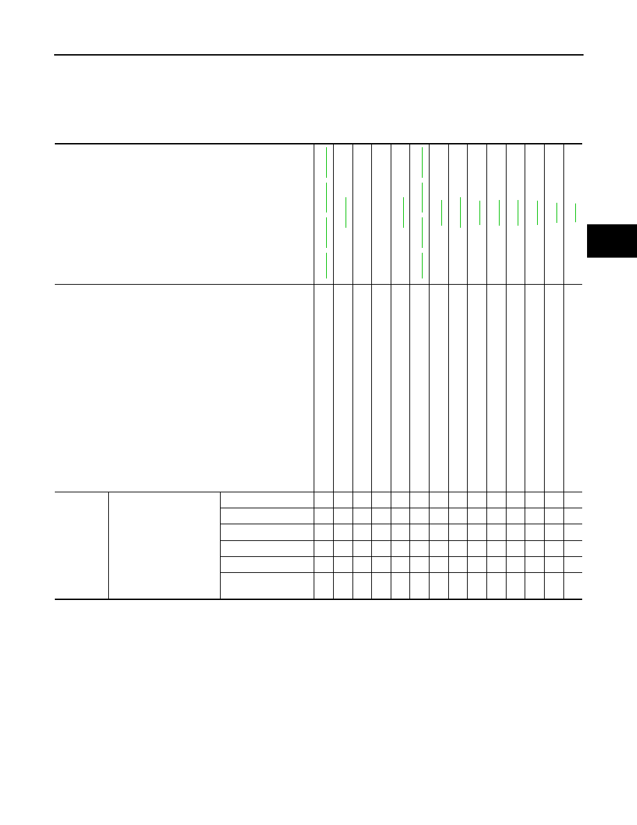
NVH Troubleshooting Chart

INFOID:0000000009561120

Use chart below to find the cause of the symptom. If necessary, repair or replace these parts.

×: Applicable

Reference

FSU-6

FS

U-

10

FSU-13

FSU-15

FSU-18

FSU-18

FSU-6

FS

U-

10

FSU-13

FSU-15

FS

U-7

FSU-13

FA

X

-6

WT

-42

WT

-41

FA

X

-8

BR-7

ST

-7

Possible cause and SUSPECTED PARTS

Imp

rop

er i

ns

ta

lla

tio

n,

 lo

os

en

es

s

Sh

oc

k ab

so

rbe

de

form

a

tio

n, dam

a

ge or 

d

ef

lec

tion

Bus

h

in

g or mo

un

t de

te

rio

ra

tio

n

Part

s interf

erence

S

p

rin

g f

ati

gu

e

Su

sp

en

si

on

 lo

os

en

es

s

In

co

rrec

t wh

ee

l a

lig

nm

en

t

S

tab

ili

ze

r ba

r fa

tig

ue

FRONT A

XLE

TI

RE

ROAD   

WHEEL

DRIVE SHAFT

BRAKE

STE

E

RING

Symptom

FRONT SUSPENSION

Noise

×

×

×

×

×

×

×

×

×

×

×

×

Shake

×

×

×

×

×

×

×

×

×

×

×

Vibration

×

×

×

×

×

×

×

×

×

Shimmy

×

×

×

×

×

×

×

×

×

×

Shudder 

×

×

×

×

×

×

×

×

Poor quality ride or 
handling

×

×

×

×

×

×

×

×

×

×

FSU-6

< PERIODIC MAINTENANCE >

FRONT SUSPENSION ASSEMBLY

PERIODIC MAINTENANCE

FRONT SUSPENSION ASSEMBLY

Inspection

INFOID:0000000009561123

COMPONENT PART

Check the mount conditions (looseness, backlash) of each component. Verify the component conditions

(wear, damage) are normal.

Ball Joint Axial End Play

1. Set the front wheels in a straight-ahead position.
2. Hold the axle side of the transverse link, and check the axial end

play by move the transverse link up and down.

CAUTION:

• Do not depress the brake pedal when measuring.

• Do not perform this inspection with the tires on the

ground.

• Be careful not to damage ball joint boot. Do not damage

the components by applying excessive force.

STRUT ASSEMBLY

Check for oil leaks or damage. Replace the parts if necessary.

Axial end play

: Refer to 

FSU-20, "Ball Joint"

.

JSEIA0444ZZ

WHEEL ALIGNMENT

FSU-7

< PERIODIC MAINTENANCE >

C

D

F

G

H

I

J

K

L

M

A

B

FSU

N

O

P

WHEEL ALIGNMENT

Inspection

INFOID:0000000009561121

PRELIMINARY INSPECTION

WARNING:

Always adjust the wheel alignment with the vehicle on a flat surface.

NOTE:

If the wheel alignment is out of specification, inspect and replace any damaged or worn rear suspension parts

before making any adjustments.
1. Check and adjust the wheel alignment with the vehicle under unladen conditions. “Unladen conditions”

means that the fuel, engine coolant, and lubricants are full; the spare tire, jack, hand tools and mats are in

designated positions.

2. Check the tires for incorrect air pressure and excessive wear.
3. Check the wheels for run out and damage. Refer to 

WT-50, "Wheel"

.

4. Check the wheel bearing axial end play. Refer to 

FAX-27, "Wheel Bearing"

.

5. Check the shock absorbers for leaks or damage.
6. Check each mount point of the suspension components for any excessive looseness or damage.
7. Check each link, arm, and the suspension member for any damage.
8. Check the vehicle height. Refer to 

FSU-21, "Wheelarch Height (Unladen*)"

.

GENERAL INFORMATION AND RECOMMENDATIONS

1. A Four-Wheel Thrust Alignment should be performed.

• This type of alignment is recommended for any NISSAN/INFINITI vehicle.

• The four-wheel “thrust” process helps ensure that the vehicle is properly aligned and the steering wheel

is centered.

• The alignment machine itself should be capable of accepting any NISSAN/INFINITI vehicle.

• The alignment machine should be checked to ensure that it is level.

2. Make sure the alignment machine is properly calibrated.

• Your alignment machine should be regularly calibrated in order to give correct information.

• Check with the manufacturer of your specific alignment machine for their recommended Service/Cali-

bration Schedule.

ALIGNMENT PROCESS

IMPORTANT: Use only the alignment specifications listed in this Service Manual. Refer to 

FSU-20, "Wheel

Alignment (Unladen*1)"

.

• When displaying the alignment settings, many alignment machines use “indicators”: (Green/red, plus or

minus, Go/No Go). Do NOT use these indicators.

- The alignment specifications programmed into your alignment machine that operate these indicators may

not be correct.

- This may result in an ERROR.

• Most camera-type alignment machines are equipped with "Rolling Compensation" method and optional

"Jacking Compensation" method to "compensate" the alignment targets or head units.

"Rolling Compensation" is the preferred method.

- If using the "Rolling Compensation" method, after installing the alignment targets or head units, push or pull

on the rear wheel to move the vehicle. Do not push or pull on the vehicle body.

- If using the "Jacking Compensation" method, after installing the alignment targets or head units, raise the

vehicle and rotate the wheels 1/2 turn in either direction.

NOTE:

Do not use the "Rolling Compensation" method if you are using sensor-type alignment equipment. 

• Follow all instructions for the alignment machine you're using for more information.

CAMBER, CASTER AND KINGPIN INCLINATION ANGLES INSPECTION

• Camber, caster, kingpin inclination angles cannot be adjusted.

• Before inspection, set the front wheels onto a turning radius gauge. Set the rear wheels onto a pad that has

the same height so the vehicle will remain horizontal.

TOTAL TOE-IN INSPECTION

Measure the total toe-in using the following procedure.

FSU-8

< PERIODIC MAINTENANCE >

WHEEL ALIGNMENT

WARNING:

• Always perform the following procedure on a flat surface.

• Make sure that no person is in front of vehicle before pushing it.
1. Bounce the front of vehicle up and down to stabilize the vehicle height (posture).
2. Push on the rear wheel to move the vehicle straight ahead about 5 m (16 ft).
3. Put a mark on base line of the tread (rear side) of each tire at the

same height of hub center. These are measuring points.

4. Measure the distance (A) from the rear side.
5. Push on the rear wheel to move the vehicle slowly ahead and to

rotate the wheels 180 degrees (1/2 turn). 

CAUTION:

If the wheels have rotated more than 180 degrees (1/2 turn),

try the above procedure again from the beginning. Do not

push vehicle backward.

6. Measure the distance (B) from the front side.

7. Use the formula below to calculate total toe-in.

• If the total toe-in is outside the specification, adjust the total toe-in. Refer to 

FSU-8, "Adjustment"

.

Adjustment

INFOID:0000000009561122

TOTAL TOE-IN

Loosen the steering outer socket. Adjust the length using the steering inner socket. 

CAUTION:

• Always evenly adjust toe-in alternately and adjust the difference between the left and right to the

standard. 

• Always hold the steering inner socket when tightening the steering outer socket. 

AFA050

SFA234AC

Total toe-in

: A - B

Total toe-in specification

: Refer to 

FSU-20, "Wheel Alignment (Unladen*1)"

.

Toe-in

: Refer to 

FSU-20, "Wheel Alignment (Un-

laden*1)"

.


Content   ..  455  456  457  458   ..