Nissan Versa Note. Manual - part 452


  Index      Nissan     Nissan Versa Note (2014 year) - Service and Repair Manual


Search            


Content   ..  450  451  452  453   ..


Nissan Versa Note. Manual - part 452


FUEL LEVEL SENSOR UNIT, FUEL FILTER AND FUEL PUMP ASSEMBLY

FL-7

< REMOVAL AND INSTALLATION >

C

D

E

F

G

H

I

J

K

L

M

A

FL

N

P

O

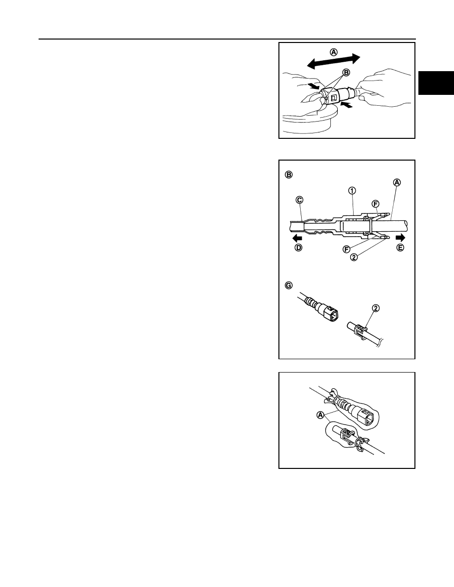
Remove the quick connector as follows:

• Hold the sides of the connector, push in tabs (B) and pull (A)

out the tube.

• If the connector and the tube are stuck together, push and pull

several times until they start to move. Then disconnect them

by pulling.

CAUTION:

• Quick connector (1) can be disconnected when the tabs

(F) are depressed completely. Do not twist it more than

necessary.

• Do not use any tools to disconnected quick connector.

• Keep resin tube (C) away from heat. Be especially careful

when welding near the resin tube.

• Prevent acid liquid such as battery electrolyte, etc. from

getting on resin tube.

• Do not bend or twist resin tube during installation and dis-

connection.

• Do not remove the remaining retainer (2) on hard tube (or

the equivalent) (A) except when resin tube or retainer is

replaced.

• When resin tube or hard tube (or the equivalent) is

replaced, also replace retainer with new one.

• To keep the connecting portion clean and to avoid dam-

age and foreign materials, cover them completely with

plastic bags (A) or something similar.

JPBIA0134ZZ

(B)

: Connection (cross-section)

(D)

: To under floor fuel line

(E)

: To fuel tank

(G)

: Disconnection

JPBIA0130ZZ

JPBIA0135ZZ

FL-8

< REMOVAL AND INSTALLATION >

FUEL LEVEL SENSOR UNIT, FUEL FILTER AND FUEL PUMP ASSEMBLY

8. Remove lock ring for fuel level sensor unit, fuel filter and fuel

pump assembly using Tool (A) by turning counterclockwise.

9. Remove fuel level sensor unit, fuel filter and fuel pump assembly.

CAUTION:

• Do not bend float arm during removal.

• Do not allow contaminants to fall inside of the fuel tank.

• Do not cause impacts such by dropping when handling components.

INSTALLATION

Installation is in the reverse order of removal.

• Install the fuel level sensor, fuel filter, and fuel pump assembly with

the fuel feed tube (C) facing the front of the vehicle as shown. Use

a new O-ring.

CAUTION:

Do not reuse O-ring.

• Connect the quick connector as follows:

- Check the connection for damage or any foreign materials.

- Align the connector with the tube, then insert the connector straight

into the tube until a click is heard.

• After the tube is connected, make sure the connection is secure by

performing the following checks:

- Pull (A) the tube and the connector to make sure they are securely

connected.

Tool number

: KV10119900 (J-45722)

ALBIA1059ZZ

: Front

(A)

: EVAP tube

(B)

: Harness connector

ALBIA0747ZZ

JPBIA0140ZZ

FUEL LEVEL SENSOR UNIT, FUEL FILTER AND FUEL PUMP ASSEMBLY

FL-9

< REMOVAL AND INSTALLATION >

C

D

E

F

G

H

I

J

K

L

M

A

FL

N

P

O

- Visually confirm that the two retainer tabs (F) are connected to the

quick connector (1). 

Inspection

INFOID:0000000009445761

INSPECTION AFTER INSTALLATION

Use the following procedure to check for fuel leaks.
1. Turn ignition switch “ON” (with engine stopped), then check fuel system connections for leaks by applying

fuel pressure to fuel piping.

2. Start engine and let it idle and check there are no fuel leaks at the fuel system connections.

(B)

: Connection (cross-section)

(C) : Resin tube

(D) : To under floor fuel line

(E)

: To fuel tank

(G) : Disconnection

JPBIA0130ZZ

FL-10

< REMOVAL AND INSTALLATION >

FUEL TANK

FUEL TANK

Exploded View

INFOID:0000000008969006

Removal and Installation

INFOID:0000000009445764

WARNING:

Read “General Precautions” when working on the fuel system. Refer to 

FL-2, "General Precaution"

.

NOTE:

When removing components such as hoses, tubes/lines, etc., cap or plug openings to prevent fluid from spill-

ing.

REMOVAL

1. Check the fuel level with the vehicle on a level surface. If the fuel

gauge indicates more than the level as shown (1/2 full), drain

the fuel from the fuel tank until the fuel gauge indicates a level at

or below as shown (1/2 full). 

• In case the fuel pump does not operate, use the following pro-

cedure.

a. Disconnect the fuel filler hose from the fuel filler tube.
b. Insert fuel tubing of less than 20 mm (0.79 in) diameter into the

fuel filler tube through the fuel filler opening to drain fuel from the

fuel filler tube.

• As a guide, if the fuel tank is full the fuel level reaches or is

less than the level on the fuel gauge as shown, when approxi-
mately 20-1/2   (5-3/8 US gal, 4-1/2 Imp gal) of fuel is drained from a full fuel tank.

2. Release the fuel pressure from the fuel lines. Refer to 

EC-135, "Work Procedure"

.

1.

Fuel tank

2.

Fuel tank mounting band (RH)

3.

Fuel tank mounting band (LH)

4.

Clamp

5.

Fuel filler hose

6.

Fuel filler tube

7.

Grommet

8.

Fuel filler cap

9.

Clamp

10. Vent hose

11.

EVAP vent line

AWBIA1592ZZ

ALBIA1130ZZ


Content   ..  450  451  452  453   ..