Nissan Versa Note. Manual - part 390
EM-76
< REMOVAL AND INSTALLATION >
[HR16DE]
CYLINDER HEAD
CYLINDER HEAD
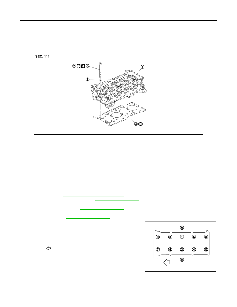
Exploded View
INFOID:0000000009444742
Cylinder Head Bolts
Removal and Installation
INFOID:0000000009444743
REMOVAL
NOTE:
When removing components such as hoses, tubes/lines, etc., cap or plug openings to prevent fluid from spill-
ing.
1. Release fuel pressure. Refer to
2. Remove the following components and related parts.
• Air duct. Refer to
EM-26, "Removal and Installation"
• Fuel tube and fuel injector. Refer to
.
• Water outlet. Refer to
CO-25, "Removal and Installation"
• Exhaust manifold. Refer to
• Front cover and timing chain. Refer to
.
• Camshaft. Refer to
.
3. Remove cylinder head loosening bolts in reverse order as
shown.
4. Remove cylinder head gasket.
INSTALLATION
1. Install new cylinder head gasket.
JPBIA4097ZZ
1.
Cylinder head assembly
2.
Cylinder head bolt
3.
Washer
4.
Cylinder head gasket
A. INSTALLATION
(A) : EXH side
(B) : INT side
: Engine front
PBIC3732E