Nissan Versa Note. Manual - part 379
 

  Index      Nissan     Nissan Versa Note (2014 year) - Service and Repair Manual


Search            


Content   ..  377  378  379  380   ..


Nissan Versa Note. Manual - part 379


EM-32

< REMOVAL AND INSTALLATION >

[HR16DE]

EXHAUST MANIFOLD

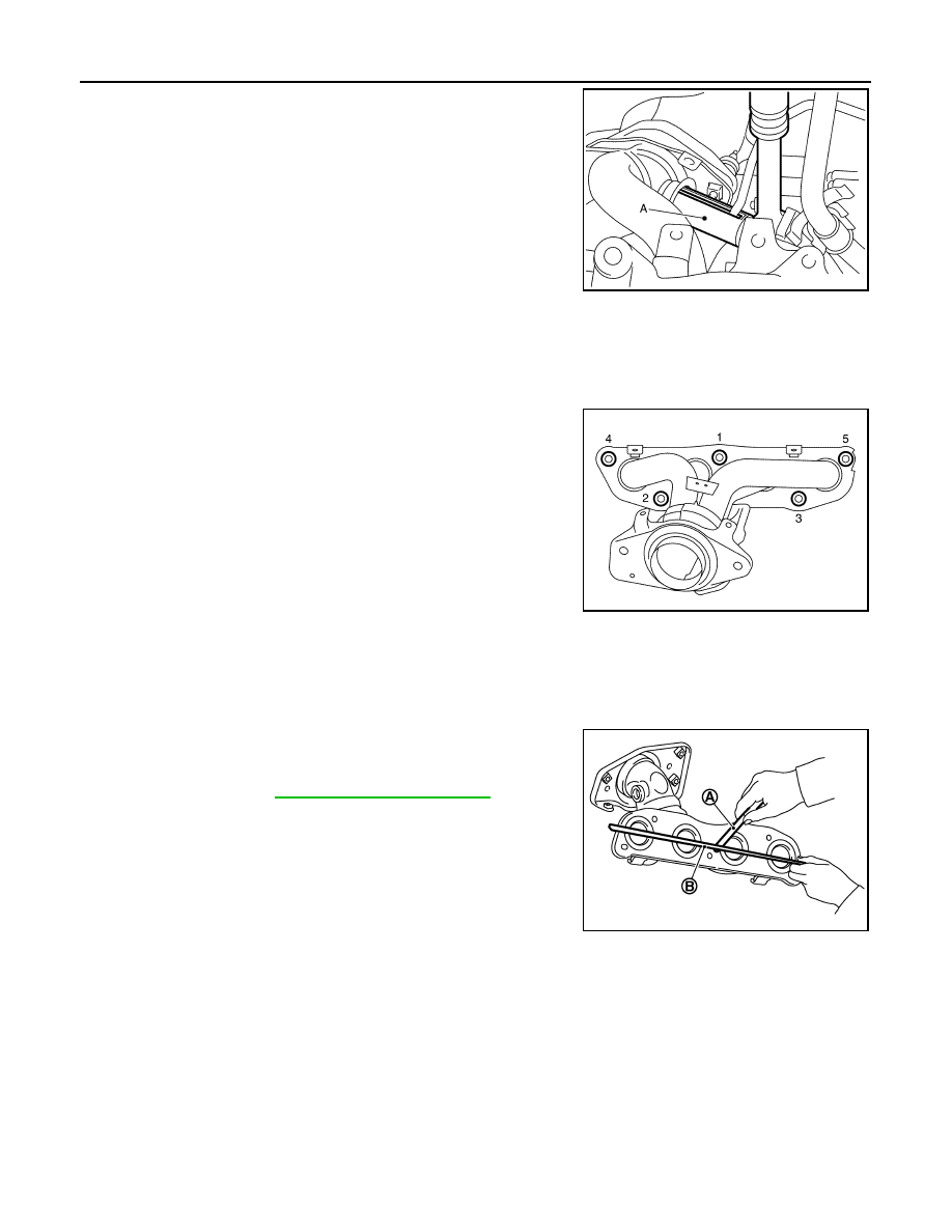
7. Use Tool (A) to remove the air-fuel ratio sensor 1 with exhaust

manifold installed on vehicle (if necessary).

CAUTION:

• Handle air-fuel ratio sensor 1 carefully and avoid impacts.

• Before installing a new air-fuel ratio sensor 1, clean the

exhaust tube threads using suitable tool and approved

anti-seize lubricant.

• If air-fuel ratio sensor is dropped onto a hard surface,

such as a concrete floor, from a height of 0.5 m or more,

discard the sensor and use a new one.

8. Remove exhaust manifold. 

• Loosen nuts in reverse order as shown.

9. Remove exhaust manifold gasket. 
10. Remove stud bolt using suitable tool from cylinder head (if necessary).

INSPECTION AFTER REMOVAL

Mounting Surface Distortion

• Using suitable tools (A) and (B), check the surface distortion of the

exhaust manifold mating surface as shown. 

• Replace exhaust manifold if it exceeds the limit.

INSTALLATION

Installation is in the reverse order of removal. Note the following:

Exhaust manifold

1. Install new exhaust manifold gasket.

CAUTION:

Tool number

: KV10117100 (   —   )

Oxygen sensor thread cleaner

:  — (J-43897-12)

Oxygen sensor thread cleaner

:  — (J-43897-18)

JPBIA4126ZZ

JPBIA4127ZZ

Limit

: Refer to 

EM-116, "Exhaust Manifold"

.

PBIC3530J

EXHAUST MANIFOLD

EM-33

< REMOVAL AND INSTALLATION >

[HR16DE]

C

D

E

F

G

H

I

J

K

L

M

A

EM

N

P

O

Do not reuse exhaust manifold gasket.

2. Tighten nuts in numerical order as shown.

3. Tighten nuts in numerical order to the specified torque again.

Air-fuel ratio sensor 1

• Use Tool (A) to install the air-fuel ratio sensor 1 (if removed).

CAUTION:

• Handle it carefully and avoid impacts.

• Before installing a new air-fuel ratio sensor 1, clean the

exhaust tube threads using suitable tool and approved anti-

seize lubricant.

• Do not over-tighten the air-fuel ratio sensor 1. Doing so may

damage the air-fuel ratio sensor 1, resulting in the MIL com-

ing on.

Installation of remaining components is in the reverse order of removal.

INSPECTION AFTER INSTALLATION

Inspection

• Start engine and raise engine speed to check for exhaust leaks.

JPBIA4127ZZ

JPBIA4127ZZ

Tool number

: KV10117100 (   —   )

Oxygen sensor thread cleaner

:  — (J-43897-12)

Oxygen sensor thread cleaner

:  — (J-43897-18)

JPBIA4126ZZ

EM-34

< REMOVAL AND INSTALLATION >

[HR16DE]

OIL PAN AND OIL STRAINER

OIL PAN AND OIL STRAINER

Exploded View

INFOID:0000000009444728

Removal and Installation (Lower Oil Pan)

INFOID:0000000009444729

REMOVAL

WARNING:

• Be careful not to get burned, engine coolant and engine oil may be hot.

• Prolonged and repeated contact with used engine oil may cause skin cancer; avoid direct skin con-

tact with used oil. If skin contact is made, wash thoroughly with soap or hand cleaner as soon as

possible.

1. Drain engine oil. Refer to 

LU-8, "Draining"

.

1.

Rear oil seal

2.

O-ring

3.

Oil pan (upper)

4.

Oil pump chain tensioner (for oil 
pump drive chain)

5.

Oil pump drive chain

6.

Crankshaft key

7.

Crankshaft sprocket

8.

Oil pump sprocket

9.

Oil pump

10. O-ring

11. O-ring

12. Oil pan drain plug

13. Drain plug washer

14. Oil pan (lower)

15. Oil filter

16. Connector bolt

17. Oil cooler

18. O-ring

19. Relief valve

A.

Refer to 

EM-37, "Removal and In-

stallation (Upper Oil Pan)"

B.

Refer to 

LU-10, "Removal and Instal-

lation"

C.

Oil pan (lower) side

AWBIA1595ZZ

OIL PAN AND OIL STRAINER

EM-35

< REMOVAL AND INSTALLATION >

[HR16DE]

C

D

E

F

G

H

I

J

K

L

M

A

EM

N

P

O

2. Loosen bolts in reverse order as shown.

3. Insert Tool (A) between oil pan (upper) and oil pan (lower).

CAUTION:

• Do not damage mating surfaces.

• Do not insert a screwdriver. This damages the mating sur-

faces.

4. Slide the Tool (A) by tapping on the side of tool with a suitable

tool to loosen the oil pan (lower).

5. Remove oil pan (lower).

INSPECTION AFTER REMOVAL

Clean debris from oil pan (lower) and from the strainer. 

INSTALLATION

CAUTION:

Do not reuse O-rings or washers.
1. Remove old liquid gasket from mating surfaces using suitable

tool (A).

• Also remove old liquid gasket from mating surface of oil pan

(upper).

• Remove old liquid gasket from the bolt holes and threads.

CAUTION:

Do not scratch or damage the mating surface when clean-

ing off old liquid gasket.

: Engine front

JSBIA1126ZZ

Tool number

: KV10111100 (J-37228)

JPBIA0276ZZ

JSBIA1127ZZ


Content   ..  377  378  379  380   ..