Nissan Versa Note. Manual - part 335


  Index      Nissan     Nissan Versa Note (2014 year) - Service and Repair Manual


Search            


Content   ..  333  334  335  336   ..


Nissan Versa Note. Manual - part 335


EC-322

< DTC/CIRCUIT DIAGNOSIS >

[HR16DE]

P0456 EVAP CONTROL SYSTEM

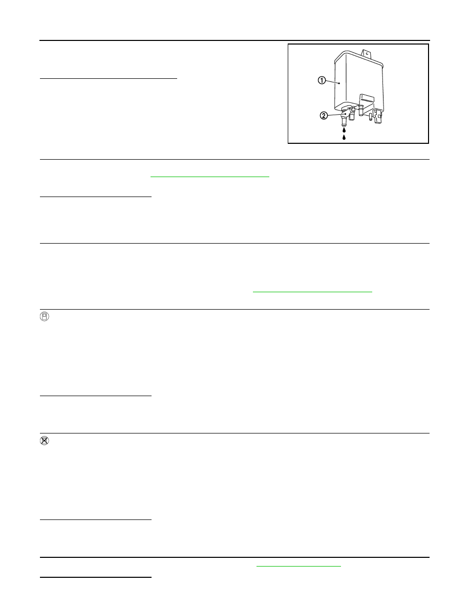
1. Remove EVAP canister (1) with EVAP canister vent control

valve (2) and EVAP control system pressure sensor attached.

2. Check if water will drain from the EVAP canister.
Does water drain from EVAP canister?

YES

>> GO TO 8.

NO-1 >> With CONSULT: GO TO 10.

NO-2 >> Without CONSULT: GO TO 11.

8.

CHECK EVAP CANISTER

Weigh the EVAP canister assembly with the EVAP canister vent control valve and EVAP control system pres-

sure sensor attached. Refer to 

FL-17, "Removal and Installation"

.

The weight should be less than 1.6 kg (3.5 lb).
Is the inspection result normal?

YES-1 >> With CONSULT: GO TO 10.

YES-2 >> Without CONSULT: GO TO 11.

NO

>> GO TO 9.

9.

DETECT MALFUNCTIONING PART

Check the following.

• EVAP canister for damage

• EVAP hose between EVAP canister and vehicle frame for clogging or poor connection

>> Repair hose or replace EVAP canister. Refer to 

FL-14, "Removal and Installation"

.

10.

CHECK EVAP CANISTER PURGE VOLUME CONTROL SOLENOID VALVE OPERATION

With CONSULT

1. Disconnect vacuum hose to EVAP canister purge volume control solenoid valve at EVAP service port.

2. Start engine and let it idle.

3. Select “PURG VOL CONT/V” in “ACTIVE TEST” mode of “ENGINE” using CONSULT.

4. Touch “Qu” on CONSULT screen to increase “PURG VOL CONT/V” opening to 100%.

5. Check vacuum hose for vacuum.

Is the inspection result normal?

YES

>> GO TO 13.

NO

>> GO TO 12.

11.

CHECK EVAP CANISTER PURGE VOLUME CONTROL SOLENOID VALVE OPERATION

Without CONSULT

1. Start engine and warm it up to normal operating temperature.

2. Stop engine.

3. Disconnect vacuum hose to EVAP canister purge volume control solenoid valve at EVAP service port.

4. Start engine and let it idle for at least 80 seconds.

5. Check vacuum hose for vacuum when revving engine up to 2,000 rpm.

Is the inspection result normal?

YES

>> GO TO 13.

NO

>> GO TO 12.

12.

CHECK VACUUM HOSE

Check vacuum hoses for clogging or disconnection. Refer to 

FL-14, "Exploded View"

.

Is the inspection result normal?

PBIB2731E

Vacuum should exist.

Vacuum should exist.

P0456 EVAP CONTROL SYSTEM

EC-323

< DTC/CIRCUIT DIAGNOSIS >

[HR16DE]

C

D

E

F

G

H

I

J

K

L

M

A

EC

N

P

O

YES

>> GO TO 13.

NO

>> Repair or reconnect the hose.

13.

CHECK EVAP CANISTER PURGE VOLUME CONTROL SOLENOID VALVE

Check the EVAP canister purge volume control solenoid valve. Refer to 

EC-295, "Component Inspection"

.

Is the inspection result normal?

YES

>> GO TO 14.

NO

>> Replace EVAP canister purge volume control solenoid valve. Refer to 

FL-14, "Exploded View"

.

14.

CHECK FUEL TANK TEMPERATURE SENSOR

Check the fuel tank temperature sensor. Refer to 

EC-256, "Component Inspection"

.

Is the inspection result normal?

YES

>> GO TO 15.

NO

>> Replace fuel level sensor unit. Refer to 

FL-6, "Removal and Installation"

.

15.

CHECK EVAP CONTROL SYSTEM PRESSURE SENSOR

Check the EVAP control system pressure sensor. Refer to 

FL-19, "Removal and Installation"

.

Is the inspection result normal?

YES

>> GO TO 16.

NO

>> Replace EVAP control system pressure sensor. Refer to 

FL-19, "Removal and Installation"

.

16.

CHECK EVAP PURGE LINE

Check EVAP purge line (pipe, rubber tube, fuel tank and EVAP canister) for cracks or improper connection.

Refer to 

EC-40, "EVAPORATIVE EMISSION SYSTEM : System Description"

.

Is the inspection result normal?

YES

>> GO TO 17.

NO

>> Repair or reconnect the hose.

17.

CLEAN EVAP PURGE LINE

Clean EVAP purge line (pipe and rubber tube) using air blower.

>> GO TO 18.

18.

CHECK EVAP/ORVR LINE

Check EVAP/ORVR line between EVAP canister and fuel tank for clogging, kink, looseness and improper con-

nection. For location, refer to 

EC-29, "On Board Refueling Vapor Recovery (ORVR)"

.

Is the inspection result normal?

YES

>> GO TO 19.

NO

>> Repair or replace hoses and tubes.

19.

CHECK RECIRCULATION LINE

Check recirculation line between fuel filler tube and fuel tank for clogging, kink, cracks, looseness and

improper connection.
Is the inspection result normal?

YES

>> GO TO 20.

NO

>> Repair or replace hose, tube or fuel filler tube.

20.

CHECK REFUELING EVAP VAPOR CUT VALVE

Check the refueling EVAP vapor cut valve. Refer to 

EC-447, "Component Inspection (Refueling EVAP vapor

cut valve)"

.

Is the inspection result normal?

YES

>> GO TO 21.

NO

>> Replace refueling EVAP vapor cut valve with fuel tank. Refer to 

FL-10, "Removal and Installation"

.

21.

CHECK FUEL LEVEL SENSOR

Check the fuel level sensor. Refer to 

MWI-46, "Component Inspection"

Is the inspection result normal?

EC-324

< DTC/CIRCUIT DIAGNOSIS >

[HR16DE]

P0456 EVAP CONTROL SYSTEM

YES

>> Check intermittent incident. Refer to 

GI-41, "Intermittent Incident"

.

NO

>> Replace fuel level sensor unit. Refer to 

FL-6, "Removal and Installation"

.

Component Inspection

INFOID:0000000009020818

1.

CHECK FUEL FILLER CAP

1. Turn ignition switch OFF.

2. Remove fuel filler cap.

3. Wipe clean valve housing.

4. Install fuel filler cap adapter (commercial service tool) to fuel

filler cap.

5. Check valve opening pressure and vacuum.

Is the inspection result normal?

YES

>> INSPECTION END

NO

>> GO TO 2.

2.

REPLACE FUEL FILLER CAP

Replace fuel filler cap.

CAUTION:

Use only a genuine fuel filler cap as a replacement. If an incorrect fuel filler cap is used, the MIL may

illuminate.

>> INSPECTION END

SEF445Y

Pressure:

15.3 - 20.0 kPa (0.156 - 0.204 kg/cm

2

, 2.22 

- 2.90 psi)

Vacuum:

6.0 to 3.3 kPa (0.061 to 0.034 kg/cm

2

0.87 to 0.48 psi)

SEF943S

P0460 FUEL LEVEL SENSOR

EC-325

< DTC/CIRCUIT DIAGNOSIS >

[HR16DE]

C

D

E

F

G

H

I

J

K

L

M

A

EC

N

P

O

P0460 FUEL LEVEL SENSOR

DTC Logic

INFOID:0000000009020819

DTC DETECTION LOGIC

NOTE:

• If DTC P0460 is displayed with DTC UXXXX, first perform the trouble diagnosis for DTC UXXXX.

• If DTC P0460 is displayed with DTC P0607, first perform the trouble diagnosis for DTC P0607. Refer

to 

EC-351, "DTC Logic"

.

When the vehicle is parked, naturally the fuel level in the fuel tank is stable. It means that output signal of the

fuel level sensor does not change. If ECM senses sloshing signal from the sensor, fuel level sensor malfunc-

tion is detected.

DTC CONFIRMATION PROCEDURE

1.

PRECONDITIONING

If DTC Confirmation Procedure has been previously conducted, always perform the following procedure

before conducting the next test.

1. Turn ignition switch OFF and wait at least 10 seconds.

2. Turn ignition switch ON.

3. Turn ignition switch OFF and wait at least 10 seconds.

>> GO TO 2.

2.

PERFORM DTC CONFIRMATION PROCEDURE

1. Start engine and wait maximum of 2 consecutive minutes.

2. Check 1st trip DTC.
Is 1st trip DTC detected?

YES

>> Proceed to 

EC-325, "Diagnosis Procedure"

.

NO

>> INSPECTION END

Diagnosis Procedure

INFOID:0000000009020820

1.

CHECK COMBINATION METER FUNCTION

Refer to 

MWI-15, "CONSULT Function"

.

Is the inspection result normal?

YES

>> CHECK INTERMITTENT INCIDENT. Refer to 

GI-41, "Intermittent Incident"

.

NO

>> Refer to 

MWI-45, "Component Function Check"

.

DTC No.

CONSULT screen terms

(Trouble diagnosis content)

DTC detecting condition

Possible cause

P0460

FUEL LEV SEN SLOSH
(Fuel level sensor circuit noise)

Even though the vehicle is parked, a 
signal being varied is sent from the 
fuel level sensor to ECM.

• Harness or connectors

(The CAN communication line is open or shorted)

• Harness or connectors

(The sensor circuit is open or shorted)

• Combination meter
• Fuel level sensor


Content   ..  333  334  335  336   ..