Nissan Versa Note. Manual - part 316


  Index      Nissan     Nissan Versa Note (2014 year) - Service and Repair Manual


Search            


Content   ..  314  315  316  317   ..


Nissan Versa Note. Manual - part 316


EC-246

< DTC/CIRCUIT DIAGNOSIS >

[HR16DE]

P0171 FUEL INJECTION SYSTEM FUNCTION

NO

>> GO TO 5.

5.

PERFORM DTC CONFIRMATION PROCEDURE-III

1. Turn ignition switch OFF and wait at least 10 seconds.

2. Start engine.

3. Maintain the following conditions for at least 10 consecutive minutes.

Hold the accelerator pedal as steady as possible.

CAUTION:

Always drive vehicle at a safe speed.

4. Check 1st trip DTC.
Is 1st trip DTC detected?

YES

>> Go to 

EC-246, "Diagnosis Procedure"

.

NO

>> INSPECTION END

Diagnosis Procedure

INFOID:0000000009020750

1.

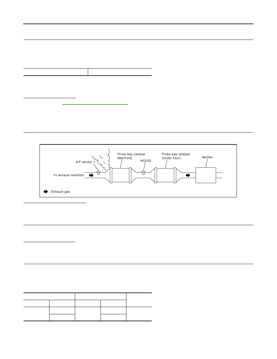
CHECK EXHAUST GAS LEAK

1. Start engine and run it at idle.

2. Listen for an exhaust gas leak before three way catalyst (manifold).

Is exhaust gas leak detected?

YES

>> Repair or replace.

NO

>> GO TO 2.

2.

CHECK FOR INTAKE AIR LEAK AND PCV HOSE

1. Listen for an intake air leak after the mass air flow sensor.

2. Check PCV hose connection.
Intake air leak detected?

YES

>> Repair or replace.

NO

>> GO TO 3.

3.

CHECK A/F SENSOR 1 INPUT SIGNAL CIRCUIT FOR OPEN AND SHORT

1. Turn ignition switch OFF.

2. Disconnect corresponding A/F sensor 1 harness connector.

3. Disconnect ECM harness connector.

4. Check the continuity between A/F sensor 1 harness connector and ECM harness connector.

5. Check the continuity between A/F sensor 1 harness connector or ECM harness connector and ground.

VHCL SPEED SE

50 – 120 km/h (31 – 75 MPH)

PBIB1216E

A/F sensor 1

ECM

Continuity

Connector

Terminal

Connector

Terminal

F12

1

F11

49

Existed

2

53

P0171 FUEL INJECTION SYSTEM FUNCTION

EC-247

< DTC/CIRCUIT DIAGNOSIS >

[HR16DE]

C

D

E

F

G

H

I

J

K

L

M

A

EC

N

P

O

6. Also check harness for short to power.
Is the inspection result normal?

YES

>> GO TO 4.

NO

>> Repair open circuit or short to ground or short to power in harness or connectors.

4.

CHECK FUEL PRESSURE

1. Release fuel pressure to zero. Refer to 

EC-135, "Work Procedure"

.

2. Install fuel pressure gauge and check fuel pressure. Refer to 

EC-135, "Work Procedure"

.

Is the inspection result normal?

YES

>> GO TO 6.

NO

>> GO TO 5.

5.

 CHECK FUEL HOSES AND FUEL TUBES

Check fuel hoses and fuel tubes for clogging.
Is the inspection result normal?

YES

>> Replace “fuel filter and fuel pump assembly”. Refer to 

FL-6, "Exploded View"

.

NO

>> Repair or replace

6.

CHECK MASS AIR FLOW SENSOR

With CONSULT

1. Install all removed parts.

2. Check “MASS AIRFLOW” in “DATA MONITOR” mode with CONSULT.

With GST

1. Install all removed parts.

2. Check mass air flow sensor signal in Service $01 with GST.

Is the measurement value within the specification?

YES

>> GO TO 7.

NO

>> Check connectors for rusted terminals or loose connections in the mass air flow sensor circuit or

grounds. Refer to 

EC-187, "DTC Logic"

.

7.

CHECK FUNCTION OF FUEL INJECTOR

With CONSULT

1. Start engine.

2. Perform “POWER BALANCE” in “ACTIVE TEST” mode with CONSULT.

3. Make sure that each circuit produces a momentary engine speed drop.

A/F sensor 1

Ground

Continuity

Connector

Terminal

F12

1

Ground

Not existed

2

ECM

Ground

Continuity

Connector

Terminal

F11

49

Ground

Not existed

53

At idling: Approximately 350 kPa (3.57 kg/cm

2

, 51 psi)

0.8 - 4.0 g/s

: at idling

2.0 - 10.0 g/s : at 2,500 rpm

0.8 - 4.0 g/s

: at idling

2.0 - 10.0 g/s : at 2,500 rpm

EC-248

< DTC/CIRCUIT DIAGNOSIS >

[HR16DE]

P0171 FUEL INJECTION SYSTEM FUNCTION

Without CONSULT

1. Let engine idle.

2. Listen to each fuel injector operating sound.

Is the inspection result normal?

YES

>> GO TO 8.

NO

>> Perform trouble diagnosis for FUEL INJECTOR. Refer

to 

EC-434, "Component Function Check"

.

8.

CHECK FUEL INJECTOR

1. Turn ignition switch OFF.

2. Confirm that the engine is cooled down and there are no fire hazards near the vehicle.

3. Disconnect all fuel injector harness connectors.

4. Remove fuel tube assembly. Refer to 

FL-6, "Removal and Installation"

.

Keep fuel hose and all fuel injectors connected to fuel tube.

5. Disconnect all ignition coil harness connectors.

6. Prepare pans or saucers under each fuel injector.

7. Crank engine for about 3 seconds.

Is the inspection result normal?

YES

>> GO TO 9.

NO

>> Replace fuel injectors from which fuel does not spray

out. Always replace O-ring with new ones. Refer to 

EM-

40, "Removal and Installation"

.

9.

CHECK INTERMITTENT INCIDENT

Refer to 

GI-41, "Intermittent Incident"

.

>> INSPECTION END

Clicking noise should be heard.

PBIB3332E

Fuel should be sprayed evenly for each fuel injector.

PBIA9666J

P0172 FUEL INJECTION SYSTEM FUNCTION

EC-249

< DTC/CIRCUIT DIAGNOSIS >

[HR16DE]

C

D

E

F

G

H

I

J

K

L

M

A

EC

N

P

O

P0172 FUEL INJECTION SYSTEM FUNCTION

DTC Logic

INFOID:0000000009020751

DTC DETECTION LOGIC

With the Air/Fuel Mixture Ratio Self-Learning Control, the actual mixture ratio can be brought closely to the

theoretical mixture ratio based on the mixture ratio feedback signal from the A/F sensor 1. The ECM calcu-

lates the necessary compensation to correct the offset between the actual and the theoretical ratios.

In case the amount of the compensation value is extremely large (The actual mixture ratio is too rich.), the

ECM judges the condition as the fuel injection system malfunction and lights up the MI (2 trip detection logic).

DTC CONFIRMATION PROCEDURE

1.

PRECONDITIONING

If DTC Confirmation Procedure has been previously conducted, always perform the following procedure

before conducting the next test.

1. Turn ignition switch OFF and wait at least 10 seconds.

2. Turn ignition switch ON.

3. Turn ignition switch OFF and wait at least 10 seconds.

>> GO TO 2.

2.

PERFORM DTC CONFIRMATION PROCEDURE-I

1. Clear the mixture ratio self-learning value. Refer to 

EC-130, "Work Procedure"

.

2. Start engine.
Is it difficult to start engine?

YES

>> GO TO 3.

NO

>> GO TO 4.

3.

RESTART ENGINE

If it is difficult to start engine, the fuel injection system has a malfunction, too.

Crank engine while depressing accelerator pedal.

NOTE:

When depressing accelerator pedal three-fourths (3/4) or more, the control system may not start the engine.

Do not depress accelerator pedal too much.
Does engine start?

YES

>> Go to 

EC-250, "Diagnosis Procedure"

.

NO

>> Remove spark plugs and check for fouling, etc.

4.

PERFORM DTC CONFIRMATION PROCEDURE-II

1. Start engine and let it idle for at least 5 minutes.

2. Check 1st trip DTC.
Is 1st trip DTC detected?

YES

>> Go to 

EC-250, "Diagnosis Procedure"

.

NO

>> GO TO 5.

5.

PERFORM DTC CONFIRMATION PROCEDURE-III

Sensor

Input signal to ECM

ECM function

Actuator

A/F sensor 1

Density of oxygen in exhaust gas
(Mixture ratio feedback signal)

Fuel injection control

Fuel injector

DTC No.

Trouble diagnosis content

DTC detecting condition 

Possible cause

P0172

Fuel injection system too rich

• Fuel injection system does not operate properly.
• The amount of mixture ratio compensation is too 

large. (The mixture ratio is too rich.)

• A/F sensor 1
• Fuel injector
• Exhaust gas leaks
• Incorrect fuel pressure
• Mass air flow sensor


Content   ..  314  315  316  317   ..