Nissan Versa Note. Manual - part 314


  Index      Nissan     Nissan Versa Note (2014 year) - Service and Repair Manual


Search            


Content   ..  312  313  314  315   ..


Nissan Versa Note. Manual - part 314


EC-238

< DTC/CIRCUIT DIAGNOSIS >

[HR16DE]

P0139 HO2S2

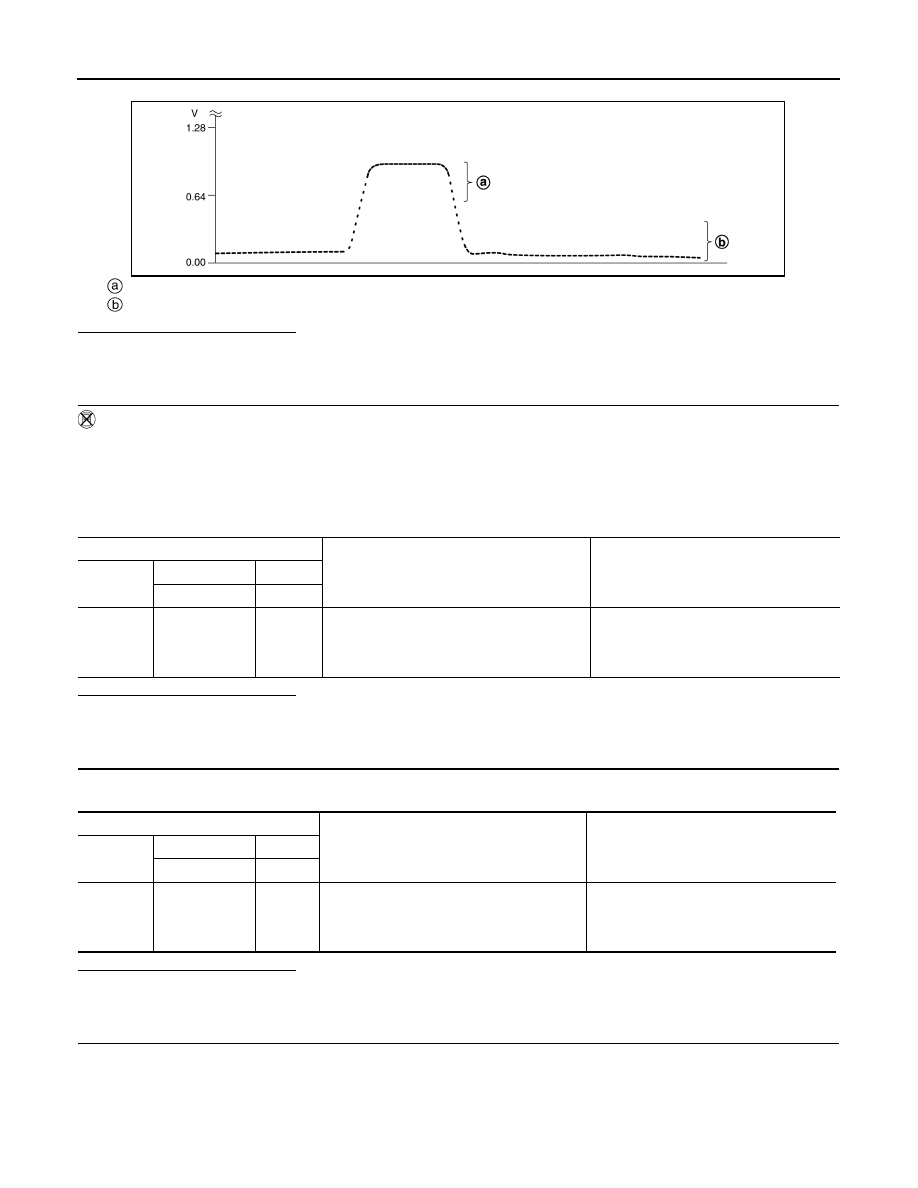
8. Check “HO2S2 (B1)” at idle speed when adjusting “FUEL INJECTION” to 

±25%.

“HO2S2 (B1)” should be above 0.78 V at least once when the “FUEL INJECTION” is +25%.
“HO2S2 (B1)” should be below 0.18 V at least once when the “FUEL INJECTION” is 

25%.

Is the inspection result normal?

YES

>> INSPECTION END

NO

>> GO TO 6.

3.

CHECK HEATED OXYGEN SENSOR 2-I

Without CONSULT

1. Start engine and warm it up to the normal operating temperature.

2. Turn ignition switch OFF and wait at least 10 seconds.

3. Start engine and keep the engine speed between 3,500 and 4,000 rpm for at least 1 minute under no load.

4. Let engine idle for 1 minute.

5. Check the voltage between ECM harness connector terminals under the following condition.

Is the inspection result normal?

YES

>> INSPECTION END

NO

>> GO TO 4.

4.

CHECK HEATED OXYGEN SENSOR 2-II

Check the voltage between ECM harness connector terminals under the following condition.

Is the inspection result normal?

YES

>> INSPECTION END

NO

>> GO TO 5.

5.

CHECK HEATED OXYGEN SENSOR 2-III

Check the voltage between ECM harness connector terminals under the following condition.

JSBIA3451ZZ

ECM

Condition

Voltage

Connector

+

Terminal

Terminal

F11

50

(HO2S2)

59

Revving up to 3,600 rpm under no load at 
least 10 times

The voltage should be above 0.78 V at 
least once during this procedure.
The voltage should be below 0.18 V at 
least once during this procedure.

ECM

Condition

Voltage

Connector

+

Terminal

Terminal

F11

50

(HO2S2)

59

Keeping engine at idle for 10 minutes

The voltage should be above 0.78 V at 
least once during this procedure.
The voltage should be below 0.18 V at 
least once during this procedure.

P0139 HO2S2

EC-239

< DTC/CIRCUIT DIAGNOSIS >

[HR16DE]

C

D

E

F

G

H

I

J

K

L

M

A

EC

N

P

O

Is the inspection result normal?

YES

>> INSPECTION END

NO

>> GO TO 6.

6.

REPLACE HEATED OXYGEN SENSOR 2

Replace malfunctioning heated oxygen sensor 2. Refer to 

EX-5, "Exploded View"

.

CAUTION:

• Discard any heated oxygen sensor which has been dropped from a height of more than 0.5 m (19.7

in) onto a hard surface such as a concrete floor; use a new one.

• Before installing new oxygen sensor, clean exhaust system threads using Oxygen Sensor Thread

Cleaner [commercial service tool (J-43897-18 or J43897-12)] and approved anti-seize lubricant (com-

mercial service tool).

>> INSPECTION END

ECM

Condition

Voltage

Connector

+

Terminal

Terminal

F11

50

(HO2S2)

59

Coasting from 80 km/h (50 MPH) in D position 
(CVT), 4th gear position (M/T)

The voltage should be above 0.78 V at 
least once during this procedure.
The voltage should be below 0.18 V at 
least once during this procedure.

EC-240

< DTC/CIRCUIT DIAGNOSIS >

[HR16DE]

P014C, P014D, P015A, P015B, A/F SENSOR 1

P014C, P014D, P015A, P015B, A/F SENSOR 1

DTC Logic

INFOID:0000000009020747

DTC DETECTION LOGIC

To judge malfunctions, this diagnosis measures response time of the A/F signal computed by ECM from the A/

F sensor 1 signal. The time is compensated by engine operating (speed and load), fuel feedback control con-

stant, and the A/F sensor 1 temperature index. Judgment is based on whether the compensated time (the A/F

signal cycling time index) is inordinately long or not.

DTC CONFIRMATION PROCEDURE

1.

PRECONDITIONING

If DTC Confirmation Procedure has been previously conducted, always perform the following procedure

before conducting the next test.

1. Turn ignition switch OFF and wait at least 10 seconds.

2. Turn ignition switch ON.

3. Turn ignition switch OFF and wait at least 10 seconds.

TESTING CONDITION:

Before performing the following procedure, confirm that battery voltage is more than 11 V at idle.
Do you have CONSULT?

YES

>> GO TO 2.

NO

>> GO TO 5.

2.

PERFORM DTC CONFIRMATION PROCEDURE-1

With CONSULT

1. Start engine and warm it up to normal operating temperature.

2. Turn ignition switch OFF and wait at least 10 seconds.

3. Turn ignition switch ON.

4. Turn ignition switch OFF and wait at least 10 seconds.

5. Start engine and keep the engine speed between 3,500 and 4,000 rpm for at least 1minute under no load.

6. Let engine idle for 1 minute.

7. Increase the engine speed up to about 3,600 rpm and keep it for 10 seconds.

8. Fully release accelerator pedal and then let engine idle for about 1 minute.

9. Check the items status of “DATA MONITOR” as follows.

NOTE:

If “PRSNT” changed to “ABSNT”, refer to 

EC-149, "Component Function Check"

.

Is “PRSNT” displayed on CONSULT screen?

YES

>> GO TO 4.

NO

>> GO TO 3.

3.

PERFORM DTC CONFIRMATION PROCEDURE-2

With CONSULT

Perform DTC confirmation procedure-1 again.
Is “PRSNT” displayed on CONSULT screen?

YES

>> GO TO 4.

NO

>> Refer to 

EC-149, "Component Function Check"

.

DTC No.

Trouble diagnosis content

DTC detecting condition

Possible Cause

P014C

Air fuel ratio (A/F) sensor 1 
(bank 1) circuit slow re-
sponse

• The response time of a A/F sensor 1 signal de-

lays more than the specified time computed by 
ECM.

• Harness or connectors

(The A/F sensor 1 circuit is open or 
shorted.)

• A/F sensor 1

P014D

P015A

Air fuel ratio (A/F) sensor 1 
(bank 1) circuit delayed re-
sponse

P015B

Data monitor item

Status

A/F SEN1 DIAG3 (B1)

PRSNT

P014C, P014D, P015A, P015B, A/F SENSOR 1

EC-241

< DTC/CIRCUIT DIAGNOSIS >

[HR16DE]

C

D

E

F

G

H

I

J

K

L

M

A

EC

N

P

O

4.

PERFORM DTC CONFIRMATION PROCEDURE-2

With CONSULT

1. Wait for about 20 seconds at idle.

2. Check the items status of “DATA MONITOR” as follows.

NOTE:

If “CMPLT” changed to “INCMP”, refer to 

EC-149, "Component Function Check"

.

Is “CMPLT” displayed on CONSULT screen?

YES

>> GO TO 5.

NO

>> Refer to 

EC-149, "Component Function Check"

.

5.

PERFORM SELF-DIAGNOSIS

With CONSULT

Check the “SELF-DIAG RESULT”.
Is any DTC detected?

YES

>> Proceed to 

EC-242, "Diagnosis Procedure"

.

NO

>> INSPECTION END

6.

CHECK AIR-FUEL RATIO SELF-LEARNING VALUE

With GST

1. Start engine and warm it up to normal operating temperature.

2. Select Service $01 with GST.

3. Calculate the total value of “Short term fuel trim” and “Long term fuel trim” indications.
Is the total percentage within 

±15%?

YES

>> GO TO 8.

NO

>> GO TO 7.

7.

DETECT MALFUNCTIONING PART

Check the following.

• Intake air leaks

• Exhaust gas leaks

• Incorrect fuel pressure

• Lack of fuel

• Fuel injector

• Incorrect PCV hose connection

• PCV  valve

• Mass air flow sensor

>> Repair or replace malfunctioning part.

8.

PERFORM DTC CONFIRMATION PROCEDURE

1. Turn ignition switch OFF and wait at least 10 seconds.

2. Turn ignition switch ON.

3. Turn ignition switch OFF and wait at least 10 seconds.

4. Start engine and keep the engine speed between 3,500 and 4,000 rpm for at least 1 minute under no load.

5. Let engine idle for 1 minute.

6. Increase the engine speed up to about 3,600 rpm and keep it for 10 seconds.

7. Fully release accelerator pedal and then let engine idle for about 1 minute.

8. Check 1st trip DTC.
Is 1st trip DTC detected?

YES

>> Proceed to 

EC-242, "Diagnosis Procedure"

.

NO

>> INSPECTION END

Data monitor item

Status

A/F SEN1 DIAG1 (B1)

CMPLT

A/F SEN1 DIAG2 (B1)


Content   ..  312  313  314  315   ..