Nissan Versa Note. Manual - part 274
EC-78
< ECU DIAGNOSIS INFORMATION >
[HR16DE]
ECM
37
(W)
40
(L)
Knock sensor
Input
[Engine is running]
• Idle speed
2.5 V
38
(LG/V)
44
(P)
Engine coolant temperature
sensor
Input
[Engine is running]
0 - 4.8 V
Output voltage varies with engine
coolant temperature.
39
(L)
68
(R)
Battery temperature sensor
Input
[Engine is running]
• Battery temperature: 25
°C (°F)
• Idle speed
3.5 V
40
(L)
—
Sensor ground
(Knock sensor shield circuit)
—
—
—
42
(L)
51
(P)
Fuel tank temperature sen-
sor
Input
[Engine is running]
0 - 4.8 V
Output voltage varies with fuel
tank temperature.
43
(SB)
68
(R)
EVAP control system pres-
sure sensor
Input
[Ignition switch: ON]
0.5 - 4.6 V
44
(P)
—
Sensor ground
(Engine coolant tempera-
ture sensor)
—
—
—
45
(G/B)
52
(LG)
Mass air flow sensor
Input
[Ignition switch ON]
• Engine stopped
0.4 V
[Engine is running]
• Warm-up condition
• Idle speed
0.8 - 1.3 V
[Engine is running]
• Warm-up condition
• Engine is revving from idle to
about 4,000 rpm
0.8 - 1.3 to 2.4 V
(Check for linear voltage rise in
response to engine being in-
creased to about 4,000 rpm.)
46
(V)
55
(G/L)
Intake air temperature sen-
sor
Input
[Engine is running]
0 - 4.8 V
Output voltage varies with intake
air temperature.
47
(Y)
60
(L)
Engine oil pressure sensor
Input
[Engine is running]
• Warm-up condition
• Idle speed
1.0 - 2.0 V
[Engine is running]
• Warm-up condition
• Engine speed: 2,000 rpm
1.5 - 3.5 V
48
(W/R)
63
(W)
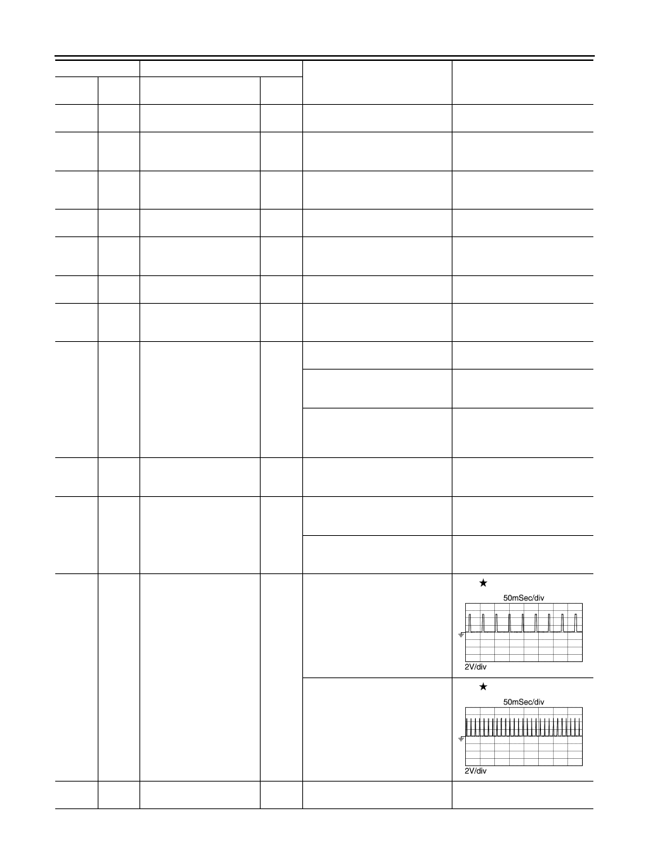
Exhaust valve timing control
position sensor
Input
[Engine is running]
• Warm-up condition
• Idle speed
NOTE:
The pulse cycle changes de-
pending on rpm at idle
4.3 V
[Engine is running]
• Engine speed: 2,000 rpm
4.3 V
49
(G/W)
108
(B)
A/F sensor 1
Input
[Ignition switch: ON]
2.2 V
Terminal No.
Description
Condition
Value
(Approx.)
+
–
Signal name
Input/
Output
JSBIA0716GB
JSBIA0717GB